(!) Since support from Microsoft will end on January 14 2020, Windows 7 user might not be able to use MISUMI website effectively. Please consider to update your system as ‘MISUMI Website system requirement’.


- inCAD Library Home
- > No.000028 Vertical Feed Mechanism
No.000028 Vertical Feed Mechanism
172
Vertical feed with a linear motion gearhead and motor
Relevant category


Flanged Linear Bushing
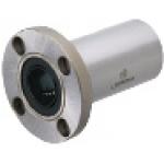
| Product name | Flanged Linear Bushings |
|---|---|
| Part number | LHFRD16 |
| Features | Full Length is 1.5 times greater than the Single Length and has an Allowable Moment that is 4.3 times greater. Suitable when there is insufficient space for the Double Type |
Selection criteria
Flanged type is suitable as a linear guide for this app. example.
Available sizes
■Flanged Linear Bushings
| Flange Shape | Outer cylinder | Ball | Retainer | Accessory Seal | Operating ambient temperature | ||
|---|---|---|---|---|---|---|---|
| Material | Hardness | Surface treatment | Material | Material | Material | ||
| Round flange ・Square flange ・Compact flange | 52100 Bearing Steel | 58HRC- | - | 52100 Bearing Steel | Resin (Duracon 90 equivalent) | Nitrile rubber | -20~80℃ |
| Electroless nickel plating | 440C Stainless Steel | ||||||
■Sizes and Dimensions
| (Shaft DIA.) | Outer cylinder diameter | Overall length | Flange | |
|---|---|---|---|---|
| Max. width | Thickness | |||
| φ6 | φ12 | 29 | 28 | 5 |
| φ8 | φ15 | 37 | 32 | |
| φ10 | φ19 | 47 | 40 | 6 |
| φ12 | φ21 | 42 | ||
| φ13 | φ23 | 43 | ||
| φ16 | φ28 | 56 | 48 | |
| φ20 | φ32 | 65 | 54 | 8 |
| φ25 | φ40 | 83 | 62 | |
| φ30 | φ45 | 90 | 74 | 10 |
Selection steps
■Linear bushing selection steps
Accuracy Info
■Accuracy info. of flanged linear bushing
| (Shaft DIA.) | Outer cylinder DIA. | Tolerance | Overall length tolerance | ||
|---|---|---|---|---|---|
| tolerance | No surface treatment | Surface treated | |||
| φ6 | 0/-0.010 | φ12 | 0/-0.013 | 0/-0.018 | ±0.3 |
| φ8 | φ15 | ||||
| φ10 | φ19 | 0/-0.016 | 0/-0.021 | ||
| φ12 | φ21 | ||||
| φ13 | φ23 | ||||
| φ16 | φ28 | ||||
| φ20 | 0/-0.012 | φ32 | 0/-0.019 | 0/-0.025 | |
| φ25 | φ40 | ||||
| φ30 | φ45 | ||||
Performance info.
■Load rating of flanged linear bushing
| (Shaft DIA.) | Basic load rating | Allowable static moment | |
|---|---|---|---|
| C (Dynamic) N | C0 (Static) N | (N・m) | |
| φ6 | 226 | 310 | 1.42 |
| φ8 | 310 | 452 | 2.12 |
| φ10 | 508 | 718 | 4.37 |
| φ12 | 634 | 814 | 6.2 |
| φ13 | 640 | 826 | 6.2 |
| φ16 | 1164 | 1448 | 13.1 |
| φ20 | 1554 | 2068 | 18.3 |
| φ25 | 1725 | 3068 | 25.3 |
| φ30 | 2440 | 3974 | 42.7 |
Technical calculations
■Life of Linear Bushing
When the linear systems are in motion with loads, rolling surfaces and races are subject to repeated stress and will show scale-flaking due to material fatigue. The total run distance until the flaking appear is the "Life" .
The rated life can be calculated with the following formula based on basic dynamic load rating and the load applied on the bushing.

- L: Rated life (km)
- fH: Hardness factor (See Fig.1)
- fT: Temperature factor (See Fig. 2)
- fC: Contact factor (See Table-3)
- fW: Load factor (See table-4)
- C: Basic dynamic load rating (N)
- P: Applicable load (N)
Hardness factor (fH)
For linear systems, the shaft that the balls contact must have sufficient hardness,If the shaft does not have sufficient hardness, the load rating decreases and life will be reduced as a result.

Fig.-1. Hardness factor

Temperature factor (fT)
When the temperature of linear systems exceed 100℃, hardness will be reduced and as a result, the allowable loads and life will be reduced.
Fig.-2. Temperature factor

Contact factor (fC)
In general, it is common to use 2 linear systems are used for 1 shaft, in general. In these cases, the load on each linear system will vary depending on machining accuracies and will not have equally distributed loads. As a result, the allowable load per linear system will very depending on the number of linear systems used on one shaft.
Table-3. Contact factor
| Number of bearings installed on one shaft. | Contact factor fC | |
|---|---|---|
| 1 | 1 | |
| 2 | 0.81 | |
| 3 | 0.72 | |
| 4 | 0.66 | |
| 5 | 0.61 | |
Load factor (fW)
To calculate load applied to the linear system, in addition to object weight, inertia force attributed to motion velocity, moment loads and variations of each over time must be obtained. However, for reciprocating motion applications, it is difficult to obtain accurate calculations due to the effects of vibrations and shocks. Therefor, use Table-2 below in order to simplify the Life Calculations.
| Application conditions | fw |
|---|---|
| No external shocks or vibrations and speed is low 15m/min or less | 1.0~1.5 |
| No significant shocks or vibration and med. speed 60m/min or less | 1.5~2.0 |
| External shocks and vibrations exist and the speed is high 60m/min or over | 2.0~3.5 |
Life in hours can be obtained by calculating travel distance per hour. When stroke length and stroke cycles are fixed, see the equation below.
- Lh: Life (Hr)
- L: Rated life (km)
- Ls: Stroke length (m)
- n1: Number of cycles per minute (cpm)

Shaft
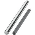
| Product name | Precision Linear Shafts - Straight Type |
|---|---|
| Part number | PSFJ16-305 |
Selection criteria
An inexpensive option for a guide component
Available sizes
■Precision Linear Shafts - Straight Type
| Material | Hardness | Surface treatment | O.D. tolerance | ||
|---|---|---|---|---|---|
| g6 | h5 | f8 | |||
| 52100 Bearing Steel | Induction hardened 58HRC〜 | − | ○ | ○ | − |
| 440C Stainless Steel | Induction hardened 56HRC〜 | ○ | ○ | − | |
| 52100 Bearing Steel | Induction hardened 58HRC〜 | Hard chrome plating Plating hardness HV750~ Plating thickness 5μ or more | ○ | ○ | − |
| 440C Stainless Steel | Induction hardened 56HRC〜 | ○ | ○ | − | |
| 52100 Bearing Steel | Induction hardened 58HRC〜 | Low temperature black chrome plating | ○ | − | − |
| 1045 Carbon Steel | − | Hard chrome plating | − | − | ○ |
| Plating hardness HV750~ | |||||
| 304 Stainless Steel | Plating thickness 10μ or more | − | − | ○ | |
■Sizes
| O.D. tolerance | O.D. | Length |
|---|---|---|
| (Configure in 1mm increments) | ||
| g6・h5 | φ3 | 10〜 400 |
| φ4 | ||
| φ5 | ||
| φ6 | 20〜 600 | |
| φ8 | 20〜 800 | |
| φ10 | ||
| φ12 | 20〜1000 | |
| φ13 | 25〜1000 | |
| φ15 | ||
| φ16 | 30〜1200 | |
| φ18 | ||
| φ20 | ||
| φ25 | 35〜1200 | |
| φ30 | 35〜1500 | |
| φ35 | ||
| φ40 | 50〜1500 | |
| φ50 | 65〜1500 | |
| f8 | φ6 | 20〜 600 |
| φ8 | 20〜 800 | |
| φ10 | ||
| φ12 | 20〜1000 | |
| φ13 | 25〜1000 | |
| φ15 | ||
| φ16 | 30〜1200 | |
| φ18 | ||
| φ20 | ||
| φ25 | 35〜1200 | |
| φ30 | 35〜1500 | |
| φ35 | ||
| φ40 | 50〜1500 | |
| φ50 | 65〜1500 |
Accuracy Info
■O.D. tolerance table
| O.D. | O.D. tolerance | ||
|---|---|---|---|
| g6 | h5 | f8 | |
| φ3 | -0.002 -0.008 | 0 -0.004 | - |
| φ4 | -0.004 -0.012 | 0 -0.005 | |
| φ5 | |||
| φ6 | -0.010 -0.028 | ||
| φ8 | -0.005 -0.014 | 0 -0.006 | -0.013 -0.035 |
| φ10 | |||
| φ12 | -0.006 -0.017 | 0 -0.008 | -0.016 -0.043 |
| φ13 | |||
| φ15 | |||
| φ16 | |||
| φ18 | |||
| φ20 | -0.007 -0.020 | 0 -0.009 | -0.020 -0.053 |
| φ25 | |||
| φ30 | |||
| φ35 | -0.009 -0.025 | 0 -0.011 | -0.025 -0.064 |
| φ40 | |||
| φ50 | |||

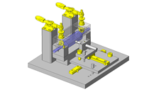
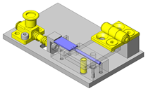
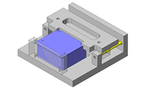
IDEA NOTE Up/down pitch feed with a linear motion gearhead and motor
Up/down pitch feed mechanism with a linear motion gearhead and motor take out equally spaced apart workpieces loaded on a tray.


-
 Terms of use of CAD data and simplified drawing data
- These terms and conditions (hereinafter referred to as “the Terms") set forth the conditions for downloading CAD data and simplified drawing data posted on https://th.misumi-ec.com/ (hereinafter referred to as the "Website") operated by MISUMI (THAILAND) CO., LTD. (hereinafter referred to as "MISUMI"). By downloading CAD data and simplified drawing data posted on the Website (hereafter referred to as “Data”), customers are deemed to have agreed to these Terms.
- 1. Purpose of Use
-
MISUMI offers the following:
1)CAD data found on the Website (3D CAD data, 3D Intermediate data and 2D CAD data) for the purpose of informing customers of the characteristics of the products offered by MISUMI or a manufacturer affiliated with MISUMI for use in their designs.
2)Simplified drawing data (in PDF format) for the purpose of checking the specifications of products. - 2. Characteristics of Data
- There may be a discrepancy in certain characteristics of products (for example: tolerance, surface roughness, chamfer, etc.) between the Data and the actual product. Furthermore, for the purpose of reducing the file size of the Data, some information such as oil groove shapes, threads, or spring shapes, may be removed from the Data.
- 3. Disclaimer
- MISUMI carefully creates the Data but makes no warranty as to the accuracy of the Data. MISUMI may at any time, and with no prior notice to customers, revise or delete Data. MISUMI assumes no responsibility for any damage or loss resulting from any revision or deletion of the Data, or any errors in said data. Customers are solely responsible for all aspects of their own designs, including those made using MISUMI’s CAD data. MISUMI may provide customers with design example data on the Website, but the quality, accuracy, functionality, safety, reliability, etc., of such data are not guaranteed. MISUMI may, at any time, and in its sole discretion, request that the customer cease its use of or destroy the Data in its possession. MISUMI may request the customer provide MISUMI documentation of such destruction.
- 4.Prohibited Acts
-
Customers or users of the Data, are prohibited from the following acts regarding the Data, in whole or in part:
(1)Requesting quotations or placing orders for products with third parties other than those authorized by MISUMI or its affiliates;
(2)Receiving quotations or orders for products from third parties by providing the Data to a third party or using the Data in their own business;
(3)Displaying links to the Website related to the Data on their own websites, etc., without MISUMI's consent;
(4)Using or reproducing the Data beyond the scope of the above-stated Purpose of Use;
(5)Modifying, altering, tampering with, translating, or adapting the Data;
(6)Selling, transferring, lending, sublicensing, or providing the Data to third parties in any way without MISUMI’s consent;
(7)Altering the content, reverse engineering, decompiling, disassembling, or analyzing the Data;
(8)Publicly disclosing or exhibiting the Data without MISUMI's consent;
(9)Using the Data for the purpose of providing products and services identical or similar to those of MISUMI;
(10)Performing acts that interfere with the proper functioning of this Website, such as acquiring Data in bulk. - 5. Copyright
-
All title and copyright in and to any information contained in the Data are owned by MISUMI or the relevant manufacturer affiliated with MISUMI and are protected by applicable copyright laws and international treaties. By downloading Data, the customer acquires no ownership rights of any kind in the intellectual property contained within. Without prior approval from MISUMI, no part of the Data may be utilized (reproduced, modified, reverse-engineered, uploaded, presented, sent, distributed, licensed, sold, or published) for any purpose other than that mentioned above.
In the event Data is found to have been to be used for any purpose other than that mentioned above or against any applicable laws, MISUMI may pursue any legal remedy available to it, which may result in forbidding the offending user from using the Data or accessing the Website. - 6. Third-Party Data
- MISUMI offers some Data provided by third parties. Such Data may be subject to separate terms and conditions, in addition to these terms. MISUMI makes no guarantee or warranty regarding Data from third parties.
- 7. Export Control
- Customers shall comply with all applicable laws and regulations regarding the export of the Data.
- 8. Amendments to the Terms
- MISUMI may, at any time, and in its sole discretion, modify these terms and conditions; any such modification will be effective immediately.
- 9. Severability
- If any term or provision of these Terms is invalid, illegal, or unenforceable in any jurisdiction, such invalidity, illegality, or unenforceability shall not affect any other term or provision of these Terms or invalidate or render unenforceable such term or provision in any other jurisdiction.
- 10.Miscellaneous
- These Terms and any disputes arising in connection therewith shall be exclusively governed by and construed in accordance with the laws of Thailand, without regard to its conflicts of law principles. The authorized courts in Thailand shall have exclusive jurisdiction to adjudicate any dispute arising in connection with these Terms.
- Revised: 16th November, 2025
CAD Download (Unit Assembly)
CAD Download: File Format
CAD Data Limitations
-
Assembly data shows the assembly drawings in the concept design phase. The sole purpose of the data is to explain the structure and functionality of the assembly and is not considered nor to be used as a final design.
You will need to edit the Data so that it meets your specific design conditions. -
Unit assembly Data consists of some sub-assemblies.
It is configured so that each sub-assembly unit can be used as it is or edited. - The Data for fabricated parts is based on easy-to-edit dimensions and shapes in sketches and histories.
- The Data including the third-part components are made by the Company.
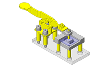
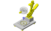
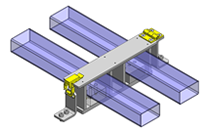
* The part in the frame is a sub-assembly unit.
-

- * Unit assembly Data consists of some sub-assemblies.
It is configured so that each sub-assembly unit can be used as it is or edited.
Application Overview
Purpose
- Workpieces on platform can be raised to adjustable height.
- Self-locking type motor prevents falling.
Target workpiece
- Workpiece
- External dims.: W147 x D167 x H12
- Weight: 0.3kg
- Tray
- External dims.: W180 x D200 x H179
- Weight: 0.6kg
- Max. weight
(5 workpieces + 5 Trays)
(0.3 x 5) + (0.6 x 5) = 4.5kg
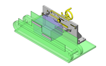
Design Specifications
Operating Conditions or Design Requirements
- Slide stroke: 116mm (Pitch 29mm x 4)
- External dims.: W480 x D350 x H537
Required Performance
- Total transferred mass: 16 kg or less
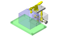
Selection Criteria for Main Components
- Motor
- Load retaining type is selected to prevent falling due to own weight.
- Linear motion gearhead
- Vertical motion type is selected to move the workpieces up/down.
- Sensor
- 2 output type sensor is selected for pitch feeding.
Design Evaluation
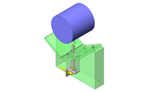
Verification of main components
- Verify the motor regarding required speed and load capacity.
- Rack speed
- Motor speed (Ns): 90~1600 r/min
- Reduction ratio of linear motion gearhead (i): 35.36
- Pitch circle DIA. of the pinion (Dp): 12mm
- Rack speed (V)
V = Ns × (1 / 60) × (1 / i) × π × Dp - Vmin = 90 × (1 / 60) × (1 / 35.36) × π × 12 = 1.6 mm/s
- Vmax = 1600 × (1 / 60) × (1 / 35.36) × π × 12 = 28.43 mm/s
- Assumed rack speed: 15mm/s, OK.
- Max. payload
- Motor torque Tm: 45N・m
- Reduction ratio of linear motion gearhead (i): 35.36
- Pitch circle DIA. of the pinion (Dp): 12mm
- Transmission efficiency by reduction ratio (η1) : 0.66
- Transmission efficiency of rack and pinion (η2): 0.9
- The maximum allowable load capacity (W):
W = Tm × I × η1 / (Dp / 2) × η2 / 9.8 = 45 × 35.36 × 0.66 / (12 / 2) × 0.9 / 9.8 = 16 kg
Total elevating mass: Workpiece + Tray + Base + Rack + Others = 4.5 + 1.3 + 1 + 2 = 8.8 kg < 16 kg
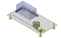
Other Design Consideration
- Pitch feeding is possible when using a photomicro sensor to detect the pitch.
- The lower most tray and the upper most tray are detected by a photoelectric switch.
- For detecting the lower most limit, another sensor and pitch detection plate are placed (Limit switch).
- For detecting the upper most limit, another sensor and a sensor flag are placed (Limit switch)
Explore Similar Application Examples

-
-

-

-
-

-

-

-

-

-

-
Relevant category
-

-

-

-

-

-

-

-

-

-

-

-

-

-

-

-

-

-

-

-

Relevant category
-

-

-
-

-

-

-

-

-

-

-

-
-

-

-

-

-

-

-
-

-

-

-

-

-

-

-

-

-

-

-

-

-

-

-

-

-

-

-

-

-

-
-

-

-

-

-

-

-

-

-

Relevant category
-

-

-

-

-

-

-

-

-

-

-

-

-

-

-

-

-

-

-

-

-

-

-

-

-

-

-

-

-

-

-

-

-

-

-

-

-

-

-

-

-

-

-

-

-

-

-

-

-

-

-

-

-

-

-

-

-
-

-

-

-
-

-

-

-

-

-

-

-

-

-

-

-

-
-

-


Payment Methods
- Bank
-
- Prompt Pay
-


- Cash
-

- Cash on Delivery
Social Media
MISUMI Contact
Copyright © MISUMI Corporation All Rights Reserved.