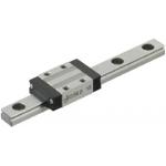
Miniature Linear Guides
| Product name | Miniature Linear Guides Standard Blocks, Light Preload, Precision Class L Configurable Type |
| Part number | SSEBLZ13-58 |
| Features | The most basic type among all the industry standard-compliant blocks. |
* Orange colored cells in the table below indicate the part numbers used in this example.
Selection criteria
Ensure running straightness.
Back to page top.
Available sizes
■Miniature Linear Guides Standard Blocks, Light Preload, Precision Class L Configurable Type
| Material | Hardness |
| 440C Stainless Steel | 56HRC- |
| Carbon Steel (Alloy Steel including SCM) | 58HRC- |
■Sizes and Dimensions.
| Number of Blocks | Block Width | Block Length | Overall Height | Rail Length |
| 1 | 17 | 23.6 | 8 | 40-130 |
| 20 | 30 | 10 | 35-275 |
| 27 | 33.9 | 13 | 45-470 |
| 32 | 42.4 | 16 | 70-670 |
| 40 | 50 | 20 | 100-700 |
| 2 | 17 | 23.6 x 2pcs. | 8 | 70-130 |
| 20 | 30 x 2pcs. | 10 | 95-275 |
| 27 | 33.9 x 2pcs. | 13 | 120-470 |
| 32 | 42.4 x 2pcs. | 16 | 150-670 |
| 40 | 50 x 2pcs. | 20 | 160-700 |
* Please see the product pages for details of selectable sizes.
Back to page top
Selection Steps
■Miniature linear guide selection steps.
- Determination on Operating Conditions.
- (Moving mass, feed rate, motion pattern, life).
↓
- Temporary selection of linear guide specifications.
- (Block type, overall height, rail length are temporarily selected according to the conditions of use.).
↓
- Basic safety check
-
- Allowable Load.
- Operating Life.
- Preload.
Back to page top.
Accuracy Info
Preload and Accuracy Reference (Standard Blocks / Light Preload / High Grade).
(μm)
| Radial Clearance | 0~+15 |
| H Dimension Tolerance | ±20 |
| Pair variation of H | 40 |
| Tolerance of dims. W2 | ±25 |
| Pair variation of W2 | 40 |
(μm)
| Rail Length (mm) |
| -80 | 81-200 | 201-250 | 251-400 | 401-500 | 501-630 | 631-700 |
| Running parallelism | 3 | 7 | 9 | 11 | 12 | 13.5 | 14 |
Back to page top.
Performance info.
Load Rating of Linear Guides (Standard block / Light Preload / High Grade).
| Overall Height | Basic Load Rating | Allowable Static Moment |
| C (Dynamic) kN | C0 (Static) kN | MA
N・m | MB
N・m | Mc
N・m |
| 6 | 0.3 | 0.6 | 0.8 | 0.8 | 1.5 |
| 8 | 0.9 | 1.5 | 4.1 | 4.1 | 5.2 |
| 10 | 1.5 | 2.5 | 5.1 | 5.1 | 10.2 |
| 13 | 2.2 | 3.3 | 8.8 | 9.5 | 16.1 |
| 16 | 3.6 | 5.4 | 21.6 | 23.4 | 39.6 |
| 20 | 5.2 | 8.5 | 48.4 | 48.4 | 86.4 |

Back to page top.
Technical Calculations
Operating Life Calculation for Linear Guides
- Operating Life.
- When the linear guide is loaded in linear reciprocating motion, scaly damages called flaking appear due to material fatigue as the stress works on the rolling elements (steel balls) and the rolling contact surfaces (rails) constantly.Total travel distance until the first flaking occurs is called Life of Linear Guides.
- Rated life.
- Rated life is the total travel distance that 90% of linear guides of the same type can reach, under the same conditions, with no occurrence of flaking damage.Rated life can be calculated with the basic dynamic load rating and the actual load applied on the linear guides, as shown below.
-

- Load must be calculated before actually using linear guides. To obtain loads during linear reciprocating motion, it is necessary to fully consider vibrations and impacts during motion as well as distribution condition of the load applied to linear guides. So, it is not easy to calculation the loads.In addition, the factors as operating temperature also significantly affect the life. Considering these conditions, the above-mentioned calculation formula will be as follows.
-

- L: Rated Life (Km).
- fH: Hardness Factor (See Fig.1).
- fT: Temperature Factor (See Fig.2).
- fC: Contact Factor (See Table-1).
- fW: Load Factor (See Table-2).
- C: Basic Dynamic Load Rating (N).
- P: Applied Load (N).
- Hardness factor (fH).
-
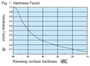
For Linear Guide applications, sufficient hardness is required for ball contact shafts. Inappropriate hardness causes less allowable load, resulting in shorter life.
Please correct the rated life with the hardness factor.
- Temperature factor (fT)
-
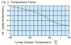
When the temperature of linear guides exceeds 100 C, the hardness of guides and shafts will be reduced, and the allowable loads will also be reduced compared to being used at room temperature, causing a reduction of life.Please correct the rated life according to the temperature factors.
* Please use Linear Guides at within the heat resistance temperature ranges shown on product pages.
- Contact factor (fC).
-
Table-1. Contact factor.
Number of blocks per rail Contact factor fC.
| 1 | 1.00 |
| 2 | 0.81 |
| 3 | 0.72 |
| 4 | 0.66 |
| 5 | 0.61 |
For actual applications, more than 2 blocks are generally used per shaft.In this case, the load applied to each block varies depending on machining precision and is not uniformly distributed.As a result, per-linear guide allowable load varies depending on the number of linear guides per rail. Please compensate the rated life with contact factors on table - 1.
- Load factor (fW).
-
Table-2. Load factor.
| Condition of Use | fw |
No shocks/vibrations,
low speed: 15m/min. or less | 1.0-1.5 |
No significant shocks/vibrations,
medium speed: 60m/min. or less | 1.5-20 |
With shocks/vibrations,
high speed: 60m/min. or more | 2.0-3.5 |
To calculate load applied to the Linear Guides, in addition to object weight, it requires inertia force attributed to motion velocity or moment loads.However, it is difficult to calculation the load accurately due to potential vibrations and shocks caused by other element than repeated start-stop motions during reciprocating motion.Thus, table-2 load factor helps simplify the life calculation.
- Applicable load calculation method.
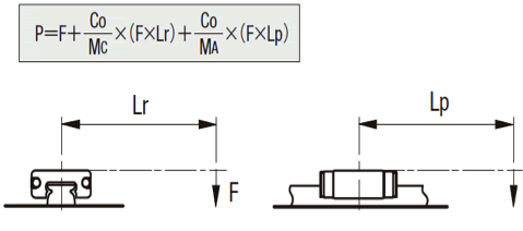
- When load is applied to the a block, convert moment load into applied load by the following formula.
-
- P: Applicable load (N).
- F: Downward load (N).
- C0: Static load rating (N).
- MA: Allowable static moment - Pitching direction (N・m).
- MC: Allowable static moment - Rolling direction (N・m).
- Lp: Load point distance (m) in pitching direction.
- Lr: Load point distance (m) in rolling direction.
Back to page top.
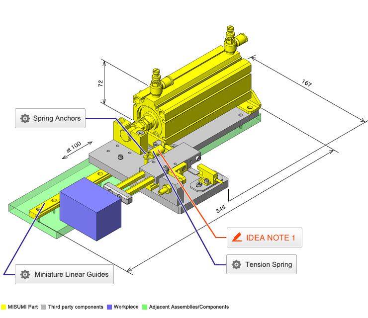
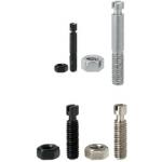
Spring Anchors
| Product name | Spring Anchors - Flat Head Screwdriver Type, with Groove |
| Part number | SBSPOZ5-30 |
| Features | Posts for Tension Springs with Straight Slot Grooves available |
* Orange colored cells in the table below indicate the part numbers used in this example.
Selection criteria
Select a groove type of spring which is capable of preventing the shift to the hook attachment of extension spring
Back to page top
Available sizes
■Spring Anchors - Flat Head Screwdriver Type, with Groove
| Material | Surface Treatment | Accessory |
| 1045 Carbon Steel | Black Oxide | Nut one pc (JIS Class 1)
Steel |
| 303 Stainless Steel | − | Nut one pc (JIS Class 1)
304 Stainless Steel |
■Sizes and Dimensions.
| O.D. | Overall Length | Threaded Section Length
(overall length - shown below) | Screw Dia.
(Coarse) | Spring Latch Shaft Dia. |
| 10 | 15 | 20 | 25 | 30 | 35 | 45 | 55 | 65 |
| φ3 | ○ | ○ | ○ | ○ | - | - | - | - | - | 4 | M3 | φ1.8 |
| φ4 | ○ | ○ | ○ | ○ | ○ | - | - | - | - | 4.2 | M4 | φ2 |
| φ5 | - | ○ | ○ | ○ | ○ | ○ | - | - | - | 6 | M5 | φ3 |
| φ6 | - | - | ○ | ○ | ○ | ○ | ○ | - | - | 7 | M6 | φ3.6 |
| φ8 | - | - | - | ○ | ○ | ○ | ○ | ○ | ○ | 7 | M8 | φ5 |
| φ10 | - | - | - | - | ○ | ○ | ○ | ○ | ○ | 7 | M10 | φ6 |
| φ12 | - | - | - | - | - | ○ | ○ | ○ | - | 8 | M12 | φ6.5 |
Back to page top
Tension Spring
| Product name | Tension Spring - Standard Lengths |
| Part number | AUA10-35 |
* Orange colored cells in the table below indicate the part numbers used in this example.
Selection criteria
In order to set the abnormal load limit
Back to page top
Available sizes
■Tension Spring - Standard Lengths
| Load Type | Material | O.D. range | Free length
range | Both ends hooked |
| Spring Steel (ASTM A228) | 304 Stainless Steel | S-shape | 90 degree S |
| Ultra light load | ○ | ○ | φ2 - 12 | 10 - 100 | ○ | - |
| Light Load | ○ | △ | φ2 - 20 | 10 - 175 | ○ | △ |
| Light/Medium Load | ○ | △ | φ2 - 20 | 10 - 175 | ○ | △ |
| Medium Load | ○ | △ | φ2 - 24 | 10 - 200 | ○ | △ |
| Medium and Heavy Load | ○ | - | φ2 - 12 | 10 - 100 | ○ | - |
| Heavy Load | ○ | △ | φ3 - 24 | 10 - 200 | ○ | △ |
Back to page top
Performance info.
■Load info. on tension spring.
| Load Type | Reference load (N) |
| Minimum | Max. |
| Ultra light load | 0.69 | 19.6 |
| Light Load | 1.86 | 78.45 |
| Light/Medium Load | 2.45 | 98.07 |
| Medium Load | 3.53 | 225.55 |
| Medium and Heavy Load | 6.47 | 83.36 |
| Heavy Load | 8.8 | 430.51 |
Back to page top
Technical calculations
■Tension spring load calculations.
P = Pi + (k × F).
P: Load (N).
Pi: Initial Tension (N).
k: Spring Constant(N/mm).
F: Deflection (mm).
Back to page top.
IDEA NOTE Prevents overload on workpiece.
To simplify the overload detection, a spring is used.


