(!) Since support from Microsoft will end on January 14 2020, Windows 7 user might not be able to use MISUMI website effectively. Please consider to update your system as ‘MISUMI Website system requirement’.


- inCAD Library Home
- > No.000140 Shuttle Transfer Mechanism
No.000140 Shuttle Transfer Mechanism
82
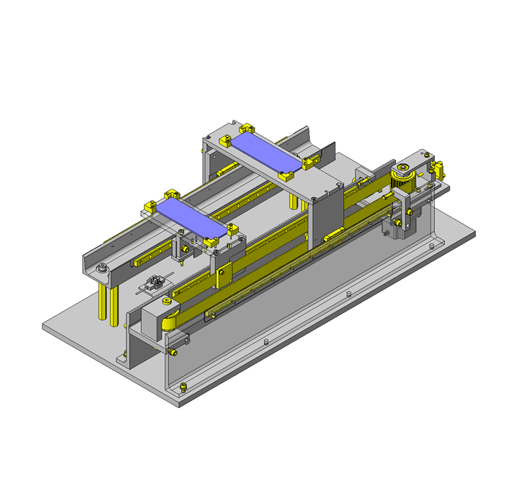
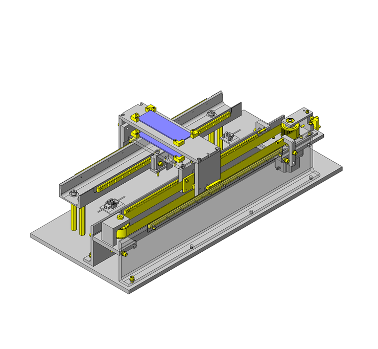
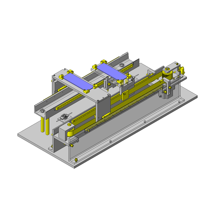
Two workpieces are transferred simultaneously through a belt mechanism.
Relevant category


High torque timing pulley

| Product name | High Torque Timing Pulleys S5M Type |
|---|---|
| Part number | HTPA28S5M250-A-P8-QTC18-M3 |
| Features | New! METRIC/ INCH Bores Available! |
Selection criteria
Aluminum alloy, which is light and commonly used for timing belt driving pulley, was selected.
Available sizes
■Timing Pulleys (S5M type)
| Material | Surface Treatment | Accessory Set Screw | |
|---|---|---|---|
| Pulley | Flanged | ||
| 2017 Aluminum Alloy (Duralumin) | 5052 Aluminum Alloy | Clear Anodize | 304 Stainless Steel |
| Black Anodize | |||
| Hard Clear Anodize | |||
| Electroless Nickel Plating | |||
| 1045 Carbon Steel | Low Carbon Steel | ― | 4137 Alloy Steel (Black Oxide) |
| Black Oxide | |||
| Electroless Nickel Plating | |||
| 304 Stainless Steel | ― | 304 Stainless Steel | |
■Sizes and Dimensions
| Number of Teeth | Nominal Width | Pulley Shape | Shaft Bore Specs. | Shaft Bore Specs. (1mm Increments) | |||||||||||||
|---|---|---|---|---|---|---|---|---|---|---|---|---|---|---|---|---|---|
| Straight Bore | Straight Bore+Tap | New JIS Keywayed Bore+Tap, Old JIS Keywayed Bore +Tap | Stepped Hole・Stepped Holes (Counterbore Holes on the Hub Side) | Both Ends Stepped Bore | |||||||||||||
| Hole Dia. | Hole Dia. | Counterbore Hole Dia. | Counterbore, Depth | Hole Dia. | Counterbore Hole Dia. | Counterbore, Depth | |||||||||||
| No Hub | With Hub | No Hub | With Hub | No Hub | With Hub | No Hub | With Hub | No Hub | With Hub | With hub, without hub | No Hub | No Hub | No Hub | ||||
| 14 | 100 150 250 | No Hub With Hub | Straight Bore Straight Bore +Tap New JIS Keywayed Bore + Tap, Old JIS Keywayed Bore + Tap Stepped Hole Stepped Hole (Counterbore Holes on the Hub Side) Both Ends Stepped Bore | 5-10 | 5-10 | 5-10 | 5-8 | 8・10 | - | 5・6 | 5・6 | 7・8 | 7・8 | (When No Hub) 2.0 ≤ Counterbore depth ≤ Ridge width - 2.0 (When with hub) 2.0 ≤ Counterbore depth ≤ Full length - 2.0 | 5・6 | 7・8 | 3-14 Total of counterbore depth ≤ Width - 3 |
| 15 | 5-10 | 5-10 | 5-10 | 5-8 | 8・10 | 5-8 | 5-8 | 7-10 | 7-10 | 5-8 | 7-10 | ||||||
| 16 | 5-12 | 5-12 | 5-12 | 5-10 | 8-12 | 8 | 5-10 | 5-10 | 7-12 | 7-12 | 5-10 | 7-12 | |||||
| 18 | 6-14 | 6-14 | 6-12 | 6-11 | 8-12 | 8・10 | 6-12 | 6-12 | 8-14 | 8-14 | 6-12 | 8-14 | |||||
| 19 | 6-16 | 6-15 | 6-16 | 6-11 | 8-16 | 8・10 | 6-14 | 6-13 | 8-16 | 8-15 | 6-14 | 8-16 | |||||
| 20 | 6-16 | 6-15 | 6-16 | 6-11 | 8-16 | 8・10 | 6-14 | 6-13 | 8-16 | 8-15 | 6-14 | 8-16 | |||||
| 22 | 7-19 | 7-19 | 7-18 | 7-15 | 8-18 | 8-12 | 7-17 | 7-17 | 9-19 | 9-19 | 7-17 | 9-19 | |||||
| 24 | 7-22 | 7-22 | 7-20 | 7-17 | 8-20 | 8-13 | 7-20 | 7-20 | 9-23 | 9-23 | 7-20 | 9-22 | |||||
| 25 | 7-22 | 7-22 | 7-20 | 7-17 | 8-20 | 8-15 | 7-20 | 7-20 | 9-23 | 9-23 | 7-20 | 9-22 | |||||
| 26 | 8-27 | 8-27 | 8-22 | 8-21 | 8-22 | 8-17 | 8-25 | 8-25 | 10-27 | 10-27 | 8-25 | 10-27 | |||||
| 28 | 8-27 | 8-27 | 8-24 | 8-22 | 8-24 | 8-18 | 8-25 | 8-25 | 10-27 | 10-27 | 8-25 | 10-27 | |||||
| 30 | 10-28 | 10-28 | 10-26 | 10-23 | 10-26 | 10-18 | 10-26 | 10-26 | 12-28 | 12-28 | 10-26 | 12-28 | |||||
| 32 | 10-32 | 10-32 | 10-28 | 10-27 | 10-28 | 10-22 | 10-30 | 10-30 | 12-32 | 12-32 | 10-30 | 12-32 | |||||
| 34 | 10-37 | 10-36 | 10-30 | 10-30 | 10-30 | 10-25 | 10-35 | 10-34 | 12-37 | 12-36 | 10-35 | 12-37 | |||||
| 36 | 10-37 | 10-36 | 10-30 | 10-30 | 10-30 | 10-25 | 10-35 | 10-34 | 12-37 | 12-36 | 10-35 | 12-37 | |||||
| 40 | 10-42 | 10-42 | 10-38 | 10-35 | 10-38 | 10-28 | 10-40 | 10-40 | 12-42 | 12-42 | 10-40 | 12-42 | |||||
| 44 | 12-50 | 12-46 | 12-42 | 12-38 | 12-40 | 12-32 | 12-48 | 12-44 | 14-50 | 14-46 | 12-48 | 14-50 | |||||
| 48 | 12-55 | 12-55 | 12-45 | 12-45 | 12-40 | 12-40 | 12-53 | 12-53 | 14-55 | 14-55 | 12-53 | 14-55 | |||||
| 50 | 12-59 | 12-59 | 12-45 | 12-45 | 12-43 | 12-43 | 12-57 | 12-57 | 14-59 | 14-59 | 12-57 | 14-59 | |||||
| 60 | 12-72 | 12-71 | 12-45 | 12-45 | 12-45 | 12-45 | 12-70 | 12-69 | 14-72 | 14-71 | 12-70 | 14-72 | |||||
| 72 | 12-80 | 12-80 | 12-65 | 12-65 | 12-50 | 12-50 | 12-80 | 12-80 | 14-92 | 14-86 | 12-75 | 14-92 | |||||
Selection steps
■Timing belt selection procedure
* Timing belt selection is made at the same time as selecting timing pulleys.
Automated selection tool is available.
http://fawos.misumi.jp/FA_WEB/pulley_us/
- Determine Operating Conditions
- Designed power, rotational speed, rotation ratio, interim shaft distance, motion pattern, etc.
↓
- Belt temporary selection
- Belt type·Belt width
↓
- Verification of specifications applicability
-
- Confirmation of calculated shaft distance, etc.
- Confirmation of belt tension and load
Technical calculations
■Timing pulley technical calculations

Timing belt clamp plates
| Product name | Timing Belt Clamp Plate - Nut Fitting Type, Single |
|---|---|
| Part number | TBCR-S5M250 |
Selection criteria
Cost Efficient
Available sizes
■Timing Belt Clamp Plate (Bottom plate Short type S5M)
| Material | Surface Treatment |
|---|---|
| A6N01-T5 | Clear Anodize |
■Sizes and Dimensions
| Belt Type | Belt Nominal Width | Vertical(mm) | Horizontal (mm) | Thickness(mm) |
|---|---|---|---|---|
| XL | 025 | 36 | 24 | 6 |
| 031 | 25 | |||
| 037 | 26 | |||
| 050 | 30 | |||
| L | 050 | 66 | 32 | 8 |
| 075 | 38 | |||
| 100 | 46 | |||
| 150 | 58 | |||
| H | 075 | 89 | 38 | 10 |
| 100 | 46 | |||
| 150 | 58 | |||
| 200 | 70 | |||
| S3M | 060 | 21 | 20 | 4 |
| 100 | 25 | |||
| 150 | 30 | |||
| S5M | 100 | 35 | 26 | 6 |
| 150 | 32 | |||
| 250 | 42 | |||
| S8M | 150 | 56 | 34 | 8 |
| 250 | 44 | |||
| 300 | 50 | |||
| 400 | 60 | |||
| TS | 100 | 35 | 26 | 6 |
| 150 | 32 | |||
| 200 | 38 | |||
| 250 | 43 | |||
| T10 | 150 | 70 | 34 | 8 |
| 200 | 40 | |||
| 250 | 44 | |||
| 300 | 50 |

Guides

| Product name | Guides- L-Shaped |
|---|---|
| Part number | WGLBC-20-10-10 |
Selection criteria
Easy to obtain
Available sizes
■Workpiece guide (L shaped compact type)
| Material | Hardness | Surface Treatment |
|---|---|---|
| 1045 Carbon Steel | ― | Black Oxide |
| Electroless Nickel Plating | ||
| 40HRC- | Black Oxide | |
| Electroless Nickel Plating | ||
| 2017 Aluminum Alloy | ― | ― |
| 304 Stainless Steel | ||
| Polyacetal | ||
| MC Nylon | ||
| Electrically conductive MC Nylon R2 | ||
| PTFE |
■Sizes and Dimensions
| On a side (mm) | Height (mm) | Installation Hole Dia. (mm) |
|---|---|---|
| 17、20 | 6-10 | 3.5 |
| 20、30 | 3.5 |
Accuracy Info.
■Accuracy information of workpiece guide
Perpendicularity: 0.05


-

-
 Terms of use of CAD data and simplified drawing data
- These terms and conditions (hereinafter referred to as “the Terms") set forth the conditions for downloading CAD data and simplified drawing data posted on https://th.misumi-ec.com/ (hereinafter referred to as the "Website") operated by MISUMI (THAILAND) CO., LTD. (hereinafter referred to as "MISUMI"). By downloading CAD data and simplified drawing data posted on the Website (hereafter referred to as “Data”), customers are deemed to have agreed to these Terms.
- 1. Purpose of Use
-
MISUMI offers the following:
1)CAD data found on the Website (3D CAD data, 3D Intermediate data and 2D CAD data) for the purpose of informing customers of the characteristics of the products offered by MISUMI or a manufacturer affiliated with MISUMI for use in their designs.
2)Simplified drawing data (in PDF format) for the purpose of checking the specifications of products. - 2. Characteristics of Data
- There may be a discrepancy in certain characteristics of products (for example: tolerance, surface roughness, chamfer, etc.) between the Data and the actual product. Furthermore, for the purpose of reducing the file size of the Data, some information such as oil groove shapes, threads, or spring shapes, may be removed from the Data.
- 3. Disclaimer
- MISUMI carefully creates the Data but makes no warranty as to the accuracy of the Data. MISUMI may at any time, and with no prior notice to customers, revise or delete Data. MISUMI assumes no responsibility for any damage or loss resulting from any revision or deletion of the Data, or any errors in said data. Customers are solely responsible for all aspects of their own designs, including those made using MISUMI’s CAD data. MISUMI may provide customers with design example data on the Website, but the quality, accuracy, functionality, safety, reliability, etc., of such data are not guaranteed. MISUMI may, at any time, and in its sole discretion, request that the customer cease its use of or destroy the Data in its possession. MISUMI may request the customer provide MISUMI documentation of such destruction.
- 4.Prohibited Acts
-
Customers or users of the Data, are prohibited from the following acts regarding the Data, in whole or in part:
(1)Requesting quotations or placing orders for products with third parties other than those authorized by MISUMI or its affiliates;
(2)Receiving quotations or orders for products from third parties by providing the Data to a third party or using the Data in their own business;
(3)Displaying links to the Website related to the Data on their own websites, etc., without MISUMI's consent;
(4)Using or reproducing the Data beyond the scope of the above-stated Purpose of Use;
(5)Modifying, altering, tampering with, translating, or adapting the Data;
(6)Selling, transferring, lending, sublicensing, or providing the Data to third parties in any way without MISUMI’s consent;
(7)Altering the content, reverse engineering, decompiling, disassembling, or analyzing the Data;
(8)Publicly disclosing or exhibiting the Data without MISUMI's consent;
(9)Using the Data for the purpose of providing products and services identical or similar to those of MISUMI;
(10)Performing acts that interfere with the proper functioning of this Website, such as acquiring Data in bulk. - 5. Copyright
-
All title and copyright in and to any information contained in the Data are owned by MISUMI or the relevant manufacturer affiliated with MISUMI and are protected by applicable copyright laws and international treaties. By downloading Data, the customer acquires no ownership rights of any kind in the intellectual property contained within. Without prior approval from MISUMI, no part of the Data may be utilized (reproduced, modified, reverse-engineered, uploaded, presented, sent, distributed, licensed, sold, or published) for any purpose other than that mentioned above.
In the event Data is found to have been to be used for any purpose other than that mentioned above or against any applicable laws, MISUMI may pursue any legal remedy available to it, which may result in forbidding the offending user from using the Data or accessing the Website. - 6. Third-Party Data
- MISUMI offers some Data provided by third parties. Such Data may be subject to separate terms and conditions, in addition to these terms. MISUMI makes no guarantee or warranty regarding Data from third parties.
- 7. Export Control
- Customers shall comply with all applicable laws and regulations regarding the export of the Data.
- 8. Amendments to the Terms
- MISUMI may, at any time, and in its sole discretion, modify these terms and conditions; any such modification will be effective immediately.
- 9. Severability
- If any term or provision of these Terms is invalid, illegal, or unenforceable in any jurisdiction, such invalidity, illegality, or unenforceability shall not affect any other term or provision of these Terms or invalidate or render unenforceable such term or provision in any other jurisdiction.
- 10.Miscellaneous
- These Terms and any disputes arising in connection therewith shall be exclusively governed by and construed in accordance with the laws of Thailand, without regard to its conflicts of law principles. The authorized courts in Thailand shall have exclusive jurisdiction to adjudicate any dispute arising in connection with these Terms.
- Revised: 16th November, 2025
CAD Download (Unit Assembly)
CAD Download: File Format
CAD Data Limitations
-
Assembly data shows the assembly drawings in the concept design phase. The sole purpose of the data is to explain the structure and functionality of the assembly and is not considered nor to be used as a final design.
You will need to edit the Data so that it meets your specific design conditions. -
Unit assembly Data consists of some sub-assemblies.
It is configured so that each sub-assembly unit can be used as it is or edited. - The Data for fabricated parts is based on easy-to-edit dimensions and shapes in sketches and histories.
- The Data including the third-part components are made by the Company.
* The part in the frame is a sub-assembly unit.
-

- * Unit assembly Data consists of some sub-assemblies.
It is configured so that each sub-assembly unit can be used as it is or edited.
Application Overview
Purpose
- A single driving mechanism to simultaneously transfer two workpieces in opposite directions.
Points for use
- Automatic mechanism in which a single driving mechanism drives two tables.
Target workpiece
- Workpiece: printed circuit board
- Outer dimensions:W150 x D50 x H3 mm
- Workpiece weight:50g
Design Specifications
Operating Conditions or Design Requirements
- Table Stroke: 385mm
- Outer dimensions: W760 x D350 x H241 mm
Required Performance
- Required accuracy:±0.5mm
Selection Basis for Main Components
- Stepping motor
- Easy positioning.
Design Evaluation
Verification of main components
- The allowable motor torque is verified to see whether the torque requirement (= load torque + acceleration torque) is satisfied.
- Stepping motor
- Conditional value = allowable motor torque T = 2.7 Nm, transfer mass M = 2.6 kg, acceleration a = 0.385m/s², operation speed NM = 180 [r/min], linear guide friction coefficient μ = 0.1 (take a larger value), acceleration time s = 0.5 s, pulley diameter D = 0.04456 m, pulley reduction ratio i1 = 1, pulley weight m = 0.33 kg, rotor inertia moment = Jo = 120 × 10⁻⁷ [kg•m²], motor reduction ratio i2 = 10, efficiency η = 0.85
- Load in operation direction = F [N ] = Ma = M × (a + μg ) = 2.6 × (0.385 + 0.98) = 3.55
- Load torque TL [N•m] = (F × D)/(2 × η × i1) = (3.55 × 0.04456)/(2 × 0.85 × 1) = 0.093
- Loading moment of inertia JL [kg•m²] = M × (π × D/2 × π)² + (m × D²)/8 = 2.6 × (0.04456/2)² + (0.33 × 0.04456²)/8 = 0.0014
- Acceleration torque Ta [Nm] = ((Jo × i2² + JL)/9.55)) × (NM/s) = ((120 × 10 - 7 × 10² + 0.0014)/9.55) × (180/0.5 ) = 0.098 (9.55 is constant)
- Required torque TM [N・m] = from TL + Ta = 0.093 + 0.098 ≈ 0.19 < 2.7 = T
-> There is no problem.
Other Design Consideration
- When the motor is rotated, two belt movement directions can be obtained, and the belt is connected to two tables that can be moved in different directions.
- As the belt design tension of 206N cannot support the allowable overhang load of 50N, bearings are added. The mechanism is assembled using the following steps to protect the motor.
(1) Temporarily tighten the bolts that fix the motor.
(2) Strain the belt.
(3) Finally tighten the bolts to fix the motor. - Positioning accuracy may be low at the end of the travel.
- Table plates are welded for strength and reinforcement.
- As a measure against failure, one microphotosensor is used for home positioning, and another microphotosensor is used for overrun prevention.
- As the upper and lower tables pass each other, there is a risk of injury.
Therefore, the unit should have a cover for the entire mechanism to reduce the operator injury risk.
Explore Similar Application Examples

-

-

-

-

-

-

-

-

-

-

-

-

-

-

-

-

-

-

-

Relevant category
-

-

-

-

-

-

-

-

-

-

-

-

-

-

-

-

-

-

-

-

-

-

-

-

-

-

-

-

-

-

-

-

-

-

-

-

-

Relevant category
-

-

-

-

-

-

-

-

-

-

-

-

-

-

-

-

-

-

-

-

-

-

-

-

-

-

-

-

-

-

-

-

-

-

-

-

-

-

-

-

-

-

-

-

-

-

-

-

-

-

-

-

-

-

-

-

-

-

-

-

-

-

-

-

-

-

-


Payment Methods
- Bank
-
- Prompt Pay
-


- Cash
-

- Cash on Delivery
Social Media
MISUMI Contact
Copyright © MISUMI Corporation All Rights Reserved.