(!) Since support from Microsoft will end on January 14 2020, Windows 7 user might not be able to use MISUMI website effectively. Please consider to update your system as ‘MISUMI Website system requirement’.


- inCAD Library Home
- > No.000233 Cleaning Chamber
No.000233 Cleaning Chamber
38
A set of nozzles are rotated to spray clean a workpiece.
Relevant category


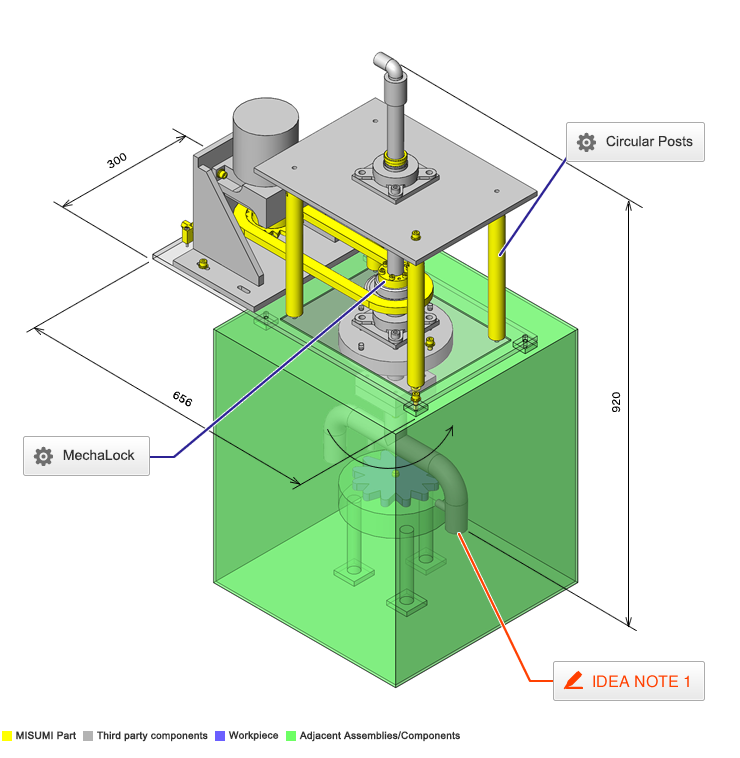
Circular Posts
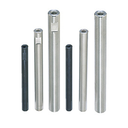
| Product name | Circular Posts - Both Ends Tapped With Standard Wrench Flat, Standard L Dimension |
|---|---|
| Part number | SETS30-300-SC30-M8-N8 |
| Features | The dimensions and thread diameter are configurable. And installation or removal of Wrench Flats can be selected. |
Selection criteria
It is suitable as a spacer to install bearings with a certain distance to each other.
Available sizes
■Circular Posts - Both Ends Tapped With Standard Wrench Flat, Standard L Dimension
| Material | Surface Treatment |
|---|---|
| 1018 Carbon Steel | - |
| Black Oxide Coating | |
| Electroless Nickel Plating | |
| Trivalent Chromate (Black) | |
| 304 Stainless Steel | - |
| 2017 Aluminum Alloy | Clear Anodize |
■Sizes and Dimensions
| Post Diameter. | Overall Length (specified in 1 mm increment) | Tapped | Wrench Groove | ||||||||||||
|---|---|---|---|---|---|---|---|---|---|---|---|---|---|---|---|
| Diameter (coarse) (select individually for each end) | Depth | Opposite Side | Slot Width | ||||||||||||
| M2.6 | M3 | M4 | M5 | M6 | M8 | M10 | M12 | M16 | M20 | M24 | |||||
| φ5 | 15-50 | ○ | ○ | Diameter x 2 | 4 | 8 | |||||||||
| φ6 | 15-50 | ○ | ○ | 5 | |||||||||||
| φ8 | 15-150 | ○ | ○ | ○ | 7 | ||||||||||
| φ10 | 20-350 | ○ | ○ | ○ | 8 | ||||||||||
| φ12 | 25-400 | ○ | ○ | ○ | 10 | 10 | |||||||||
| φ15 | 30-500 | ○ | ○ | ○ | 13 | ||||||||||
| φ20 | 40-500 | ○ | ○ | ○ | ○ | 17 | |||||||||
| φ25 | 50-600 | ○ | ○ | ○ | ○ | ○ | 22 | ||||||||
| φ30 | 60-700 | ○ | ○ | ○ | ○ | ○ | ○ | 27 | 15 | ||||||
| φ35 | 75-800 | ○ | ○ | ○ | ○ | ○ | ○ | 30 | 15 | ||||||
| φ40 | 75-900 | ○ | ○ | ○ | ○ | ○ | 36 | 20 | |||||||
| φ50 | 75-1000 | ○ | ○ | ○ | ○ | 41 | 20 | ||||||||
Accuracy Info
■Accuracy of Post Diameter
| Material | Surface Treatment | Tolerance |
|---|---|---|
| 1018 Carbon Steel | - | 0/-0.1 |
| Black Oxide Coating | ||
| Electroless Nickel Plating | ||
| Trivalent Chromate(Black) | ±0.05 | |
| 304 Stainless Steel | - | 0/-0.1 |
| 2017 Aluminum Alloy | Clear Anodize |

MechaLock

| Product name | Keyless Bushings - Compact |
|---|---|
| Part number | MLRS30 |
| Features | A hub (such as pulleys, gears and sprockets) can be easily connected with a shaft by screwing. |
Selection criteria
It is suitable for connecting a pipe member for which key groove is not available to a sprocket.
Risk info.
Deformation of pipe due to over-tightening bolt.
Available sizes
■Keyless Bushings - Compact
| Body material | Surface Treatment |
|---|---|
| 1045 Carbon Steel | - |
| 1045 Carbon Steel | Electroless Nickel Plating |
| 304 Stainless Steel | - |
■Sizes and Dimensions
| Shaft Hole Dia. | Outer Ring O.D. (pilot) | Inner Ring O.D. (shoulder) | Shoulder Height | Pilot Length. |
|---|---|---|---|---|
| φ18 | φ26 | φ46 | 16 | 14 |
| φ19 | φ27 | φ47 | ||
| φ20 | φ28 | φ48 | ||
| φ22 | φ32 | φ52 | 16 | |
| φ24 | φ34 | φ54 | ||
| φ25 | ||||
| φ28 | φ39 | φ59 | 20 | |
| φ30 | φ41 | φ61 | ||
| φ32 | φ43 | φ63 | ||
| φ35 | φ47 | φ67 | 22 | |
| φ38 | φ50 | φ70 | ||
| φ40 | φ53 | φ73 | ||
| φ42 | φ55 | φ75 | ||
| φ45 | φ59 | φ84 | 20.5 | 30 |
| φ48 | φ62 | φ87 | ||
| φ50 | φ65 | φ90 |
Accuracy Info
■Recommended Tolerance of Applicable Shaft and Hub
| Tolerance | Finish Surface Roughness | |
|---|---|---|
| Shaft O.D. | h7(g6) | Ra1.6 or less |
| Hub I.D. | H7 | Ra3.2 or less |
Performance info.
■MechaLock Compact Type (With Centering Function)
| Shaft Hole Dia. | 1045 Carbon Steel/- | 1045 Carbon Steel/Electroless Nickel Plating | 304 Stainless Steel /- | ||||||
|---|---|---|---|---|---|---|---|---|---|
| Max. Allowable Torque (N・m) | Allowable Thrust Load (kN) | Screw Tightening Torque (N・m) | Max. Allowable Torque (N・m) | Allowable Thrust Load (kN) | Screw Tightening Torque (N・m) | Max. Allowable Torque (N・m) | Allowable Thrust Load (kN) | Screw Tightening Torque (N・m) | |
| φ18 | 210 | 23.2 | 14 | 210 | 23.2 | 14 | 68 | 7.4 | 9.6 |
| φ19 | 221 | 221 | 71 | ||||||
| φ20 | 233 | 233 | 75 | ||||||
| φ22 | 256 | 256 | 83 | ||||||
| φ24 | 279 | 279 | 90 | ||||||
| φ25 | 291 | 291 | 94 | ||||||
| φ28 | 488 | 34.8 | 488 | 34.8 | 157 | 11.1 | |||
| φ30 | 523 | 523 | 168 | ||||||
| φ32 | 558 | 558 | 180 | ||||||
| φ35 | 813 | 46.4 | 813 | 46.4 | 262 | 14.9 | |||
| φ38 | 883 | 883 | 284 | ||||||
| φ40 | 929 | 929 | 299 | ||||||
| φ42 | 976 | 976 | 314 | ||||||
| φ45 | 1910 | 84.5 | 34 | 1910 | 84.5 | 34 | 620 | 27.5 | 23.6 |
| φ48 | 2040 | 2040 | 670 | ||||||
| φ50 | 2120 | 2120 | 690 | ||||||

-
 Terms of use of CAD data and simplified drawing data
- These terms and conditions (hereinafter referred to as “the Terms") set forth the conditions for downloading CAD data and simplified drawing data posted on https://th.misumi-ec.com/ (hereinafter referred to as the "Website") operated by MISUMI (THAILAND) CO., LTD. (hereinafter referred to as "MISUMI"). By downloading CAD data and simplified drawing data posted on the Website (hereafter referred to as “Data”), customers are deemed to have agreed to these Terms.
- 1. Purpose of Use
-
MISUMI offers the following:
1)CAD data found on the Website (3D CAD data, 3D Intermediate data and 2D CAD data) for the purpose of informing customers of the characteristics of the products offered by MISUMI or a manufacturer affiliated with MISUMI for use in their designs.
2)Simplified drawing data (in PDF format) for the purpose of checking the specifications of products. - 2. Characteristics of Data
- There may be a discrepancy in certain characteristics of products (for example: tolerance, surface roughness, chamfer, etc.) between the Data and the actual product. Furthermore, for the purpose of reducing the file size of the Data, some information such as oil groove shapes, threads, or spring shapes, may be removed from the Data.
- 3. Disclaimer
- MISUMI carefully creates the Data but makes no warranty as to the accuracy of the Data. MISUMI may at any time, and with no prior notice to customers, revise or delete Data. MISUMI assumes no responsibility for any damage or loss resulting from any revision or deletion of the Data, or any errors in said data. Customers are solely responsible for all aspects of their own designs, including those made using MISUMI’s CAD data. MISUMI may provide customers with design example data on the Website, but the quality, accuracy, functionality, safety, reliability, etc., of such data are not guaranteed. MISUMI may, at any time, and in its sole discretion, request that the customer cease its use of or destroy the Data in its possession. MISUMI may request the customer provide MISUMI documentation of such destruction.
- 4.Prohibited Acts
-
Customers or users of the Data, are prohibited from the following acts regarding the Data, in whole or in part:
(1)Requesting quotations or placing orders for products with third parties other than those authorized by MISUMI or its affiliates;
(2)Receiving quotations or orders for products from third parties by providing the Data to a third party or using the Data in their own business;
(3)Displaying links to the Website related to the Data on their own websites, etc., without MISUMI's consent;
(4)Using or reproducing the Data beyond the scope of the above-stated Purpose of Use;
(5)Modifying, altering, tampering with, translating, or adapting the Data;
(6)Selling, transferring, lending, sublicensing, or providing the Data to third parties in any way without MISUMI’s consent;
(7)Altering the content, reverse engineering, decompiling, disassembling, or analyzing the Data;
(8)Publicly disclosing or exhibiting the Data without MISUMI's consent;
(9)Using the Data for the purpose of providing products and services identical or similar to those of MISUMI;
(10)Performing acts that interfere with the proper functioning of this Website, such as acquiring Data in bulk. - 5. Copyright
-
All title and copyright in and to any information contained in the Data are owned by MISUMI or the relevant manufacturer affiliated with MISUMI and are protected by applicable copyright laws and international treaties. By downloading Data, the customer acquires no ownership rights of any kind in the intellectual property contained within. Without prior approval from MISUMI, no part of the Data may be utilized (reproduced, modified, reverse-engineered, uploaded, presented, sent, distributed, licensed, sold, or published) for any purpose other than that mentioned above.
In the event Data is found to have been to be used for any purpose other than that mentioned above or against any applicable laws, MISUMI may pursue any legal remedy available to it, which may result in forbidding the offending user from using the Data or accessing the Website. - 6. Third-Party Data
- MISUMI offers some Data provided by third parties. Such Data may be subject to separate terms and conditions, in addition to these terms. MISUMI makes no guarantee or warranty regarding Data from third parties.
- 7. Export Control
- Customers shall comply with all applicable laws and regulations regarding the export of the Data.
- 8. Amendments to the Terms
- MISUMI may, at any time, and in its sole discretion, modify these terms and conditions; any such modification will be effective immediately.
- 9. Severability
- If any term or provision of these Terms is invalid, illegal, or unenforceable in any jurisdiction, such invalidity, illegality, or unenforceability shall not affect any other term or provision of these Terms or invalidate or render unenforceable such term or provision in any other jurisdiction.
- 10.Miscellaneous
- These Terms and any disputes arising in connection therewith shall be exclusively governed by and construed in accordance with the laws of Thailand, without regard to its conflicts of law principles. The authorized courts in Thailand shall have exclusive jurisdiction to adjudicate any dispute arising in connection with these Terms.
- Revised: 16th November, 2025
CAD Download (Unit Assembly)
CAD Download: File Format
CAD Data Limitations
-
Assembly data shows the assembly drawings in the concept design phase. The sole purpose of the data is to explain the structure and functionality of the assembly and is not considered nor to be used as a final design.
You will need to edit the Data so that it meets your specific design conditions. -
Unit assembly Data consists of some sub-assemblies.
It is configured so that each sub-assembly unit can be used as it is or edited. - The Data for fabricated parts is based on easy-to-edit dimensions and shapes in sketches and histories.
- The Data including the third-part components are made by the Company.
* The part in the frame is a sub-assembly unit.
-

- * Unit assembly Data consists of some sub-assemblies.
It is configured so that each sub-assembly unit can be used as it is or edited.
Application Overview
Purpose
- Workpiece is cleaned by spraying cleaning solution from a set of rotating arm nozzles where the solution is flowed through the pipe rotating arms.
- A trap door is equipped for workpiece entry and exit.
Points for use
- Rotation is driven by belt, pulley, and motor.
Target workpiece
- Gear
- Exterior shape: φ120 x H 20mm
- Workpiece weight: 1kg
Design Specifications
Operating Conditions or Design Requirements
- External dimension: W 656 x D 300 x H 920mm
Motor - Capacity: 0.1kw
- Reduction Ratio: 1/40
- Torque: 19.6 N・m (60Hz)
- Rotation speed: 45 rpm (60Hz)
Required Performance
- Weight of rotating arm: 100N
- Flow rate per nozzle: 6(liter/min)
(currently, 12liter/min per 2 nozzles)
Selection Criteria for Main Components
- Motor
- Motor that generates the required torque to rotate the arm is selected.
- Nozzle
- An even fan-shaped nozzle is selected for cleaning evenly.
Design Evaluation
Verification of main components
- The motor is selected so as to satisfy the load torque.
- Motor
- Condition value: Weight of rotating arm: 100N, safety margin ratio: 2, sprocket pitch circle diameter: 101.48mm
- Load torque of motor T = 1/2 x sprocket pitch circle diameter(m) x weight of rotating arm(N) x safety margin rate, thus,
T = 1/2 x 0.10148 x 100 x 2 = 10.1N・m < 19.6N・m (rated torque)
-> Select motor of 0.1kW
Other Design Consideration
- Select rotating arm that does not interfere with workpiece.
- Rotation speed is adjusted by adjusting the sprocket sizes.
- Water is used as the cleaning solution. Adjustment is made by changing pressure using regulator, etc.
- Door interlock is necessary for the trap door during cleaning.
- The tank is to be drained at the bottom after cleaning.
- Using stainless piping due to extensive exposure to potentially corrosive fluids.
Explore Similar Application Examples

-

-

-

-
-

-

-

-

-

-

-
-

-

-

-

-

-

-

-

-

-

-

-

-

-

-

-

Relevant category
-

-

-

-

-

-

-

-

-

-

-

-

-

-

-

-

-

-

-

-

-

-

-

-

-

-

-

-

-

-

-

-

-

-

-

-

-

-

-

-

-

-

-

-

-

-

-

-


Payment Methods
- Bank
-
- Prompt Pay
-


- Cash
-

- Cash on Delivery
Social Media
MISUMI Contact
Copyright © MISUMI Corporation All Rights Reserved.