(!) Since support from Microsoft will end on January 14 2020, Windows 7 user might not be able to use MISUMI website effectively. Please consider to update your system as ‘MISUMI Website system requirement’.


- inCAD Library Home
- > No.000187 Traverse Mechanism for Heavy Workpieces
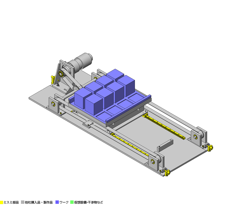
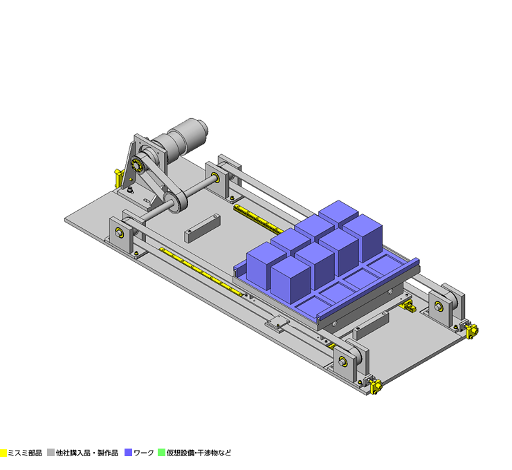
No.000187 Traverse Mechanism for Heavy Workpieces
50
Belt driven linear motion
Relevant category


Linear Guides for Extra Super Heavy Load

| Product name | Linear Guides - Extra Super Heavy Load, With Resin Retainer, Interchangeable, Light Preload |
|---|---|
| Part number | SE2RZ36-1120 |
| Features | Recirculating bearing balls are separated by resin retainers resulting in low-noise and smooth movements of the guide. |
Selection criteria
Choose the size based on workload.
Available sizes
■Linear Guides for Extra Super Heavy Load with Plastic Retainers, Interchangeable, Light Preload
| Material | Hardness |
|---|---|
| Carbon Steel | 58HRC- |
■Sizes and Dimensions
| Number of Blocks | Block Width | Block Length | Overall Height | Rail Length |
|---|---|---|---|---|
| 1 | 44 | 91.8 | 30 | 220-1960 |
| 48 | 107 | 36 | 220-1960 | |
| 60 | 124.6 | 42 | 280-1960 | |
| 2 | 44 | 91.8×2 pcs. | 30 | 220-1960 |
| 48 | 107×2 pcs. | 36 | 220-1960 | |
| 60 | 124.6 x 2pcs. | 42 | 280-1960 |
* Please see the product pages for details of selectable sizes.
Selection Steps
Linear guide selection steps
- Determine application conditions
- (Moving mass, feed rate, motion pattern, life)
↓
- Temporary selection of linear guide specifications
- (Block type, overall height, rail length are temporarily selected according to the conditions of use.)
↓
- Basic safety check
-
- Allowable Load
- Operating Life
- Preload
Accuracy Info
■Preload and Accuracy Reference (Linear Guides for Extra Super Heavy Load with Plastic Retainers, Interchangeable, Light Preload)
(μm)
| Radial Clearance | H30・H36 | -5~0 |
|---|---|---|
| H42 | -7~0 | |
| H Dimension Tolerance | ±20 | |
| Pair variation of H | 15 | |
| Tolerance of dims. W2 | ±30 | |
| Pair variation of W2 | 25 | |
Performance info.
■Linear guide performance info. (Linear Guides for Extra Super Heavy Load with Plastic Retainers, Interchangeable, Light Preload)
| Overall Height | Basic Load Rating | Allowable Static Moment | |||
|---|---|---|---|---|---|
| C (Dynamic) kN | C0 (Static) kN | MA N・m | MB N・m | Mc N・m | |
| 30 | 21.6 | 44.5 | 360 | 305 | 298 |
| 36 | 32.0 | 62.5 | 615 | 515 | 490 |
| 42 | 46.0 | 91.5 | 1000 | 885 | 870 |
Technical Calculations
Operating Life Calculation for Linear Guides
- Operating Life
- When the linear guide is loaded in linear reciprocating motion, scaly damages called flaking appear due to material fatigue as the stress works on the rolling elements (steel balls) and the rolling contact surfaces (rails) constantly. Total travel distance until the first flaking occurs is called the life of linear guides.
- Rated Life
- Rated life is the total travel distance that 90% of linear guides of the same type can reach, under the same conditions, with no occurrence of flaking damage. Rated life can be calculated with the basic dynamic load rating and the actual load applied on the linear guides, as shown below.
-
- Load must be calculated before actually using linear guides. To obtain loads during linear reciprocating motion, it is necessary to fully consider vibrations and impacts during motion as well as distribution condition of the load applied to linear guides. So, it is not easy to calculation the loads. Operating temperature also critically affects the life. Considering these conditions, the above-mentioned calculation formula will be as follows.
-
- L: Rated Life (km)
- fH: Hardness Factor (See Fig-1)
- fT: Temperature Factor (See Fig-2)
- fC: Contact Factor (See Table-1)
- fW: Load Factor (See Table-2)
- C: Basic Dynamic Load Rating (N)
- P: Applicable Load (N)
- Hardness factor (fH)
-
For liner guide applications, sufficient hardness is required for ball contact shafts. Inappropriate hardness causes less allowable load, resulting in shorter life.
Please correct the rated life with the hardness factor.
- Temperature factor (fT)
-
When the temperature of linear guides exceeds 100°C, the hardness of guides and shafts will be reduced, and the allowable loads will also be reduced compared to being used at room temperature, causing a reduction of life. Please correct the rated life with the temperature factor.
* Please use Linear Guides at within the heat resistance temperature ranges shown on product pages.
- Contact factor (fC)
-
Table-1. Contact factor
Number of blocks per rail Contact factor fC
1 1.00 2 0.81 3 0.72 4 0.66 5 0.61 For actual applications, more than two blocks are generally used per shaft. In this case, the load applied to each block varies depending on machining precision and is not uniformly distributed. As a result, per-block allowable load varies depending on the number of blocks per rail. Please compensate the rated life with contact factors on Table-1.
- Load Factor (fW)
-
Table-2. Load factor
Condition of Use fw No shocks / vibrations, low
speed: 15 m/min. or less1.0-1.5 No significant shocks / vibrations,
medium speed: 60 m/min. or less1.5-20 With shocks / vibrations,
high speed: 60 m/min. or more2.0-3.5 To calculate load applied to the Linear Guides, in addition to object weight, it requires inertia force attributed to motion velocity or moment loads. However, it is difficult to calculation the load accurately due to potential vibrations and shocks caused by other element than repeated start-stop motions during reciprocating motion. Thus, Table-2 load factor helps simplify the life calculation.
- Applicable load calculation method
- When load is applied to the a block, convert moment load into applied load by the following formula.
-
- P: Applicable Load (N)
- F: Downward load (N)
- C0: Static load rating (N)
- MA: Allowable Static Moment - Pitching Direction (N・m)
- MC: Allowable Static Moment - Rolling Direction (N・m)
- Lp: Load point distance (m) in pitching Direction
- Lr: Load point distance (m) in rolling direction

MechaLock
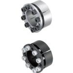
| Product name | Keyless Bushings - Standard |
|---|---|
| Part number | MLHS35 |
| Features | A hub (such as pulleys, gears and sprockets) can be easily connected with shaft by tightening mechalock screws. |
Selection criteria
Size according to pulley size, shaft size and allowable transmitted torque.
Available sizes
■MechaLock Standard Type (with Centering Function)
| Body Material | Surface Treatment |
|---|---|
| 1045 Carbon Steel | − |
| Black Oxide | |
| Electroless Nickel Plating | |
| 304 Stainless Steel | − |
■Sizes and Dimensions
| Shaft Bore Dia. | Outer Ring Dia. (pilot) | Inner Ring O.D. (shoulder) | Shoulder Height | Pilot Length |
|---|---|---|---|---|
| φ28 | φ46 | φ50 | 3.5 | 17.3 |
| φ30 | φ48 | φ52 | ||
| φ32 | φ50 | φ54 | 18.3 | |
| φ35 | φ57 | φ62 | 4 | 19.5 |
| φ38 | φ60 | φ65 | 20 | |
| φ40 | φ62 | φ67 | 20.5 | |
| φ42 | φ64 | φ69 | ||
| φ45 | φ67 | φ72 | 21 |
Accuracy Info
■Recommended Tolerance of Applicable Shaft and Hub
| Tolerance | Finish Surface Roughness | |
|---|---|---|
| Shaft O.D. | h7(g6) | Ra1.6 or less |
| Hub I.D. | H7 | Ra3.2 or less |
Performance info.
■Load info of the MechaLock Standard Type (with Centering Function)
| Shaft Bore Dia. | 1045 Carbon Steel / -, 1045 Carbon Steel / (Black Oxide) | 1045 Carbon Steel / Electroless Nickel Plating | 304 Stainless Steel/- | |||||||
|---|---|---|---|---|---|---|---|---|---|---|
| Max Allowable Torque | Allowable Thrust Load | Screw Tightening Torque | Screw Tightening Torque | Max. Allowable Torque | Allowable Thrust Load | Screw Tightening Torque | Max Allowable Torque | Allowable Thrust Load | Screw Tightening Torque | |
| (N・m) | (N・m) | |||||||||
| (N・m) | (kN) | No Surface Treatment | Black Oxide | (N・m) | (kN) | (N・m) | (N・m) | (kN) | (N・m) | |
| φ28 | 380 | 27 | 8.8 | 7.5 | 295 | 21.1 | 8.8 | 213.8 | 15.2 | 5.6 |
| φ30 | 410 | 396 | 26.4 | 229.5 | 15.3 | |||||
| φ32 | 440 | 423 | 244.2 | 15.2 | ||||||
| φ35 | 720 | 41.1 | 15.7 | 12.7 | 548 | 31.3 | 15.7 | 301.1 | 17.16 | 9.6 |
| φ38 | 770 | 40.2 | 741 | 39 | 409 | 21.48 | ||||
| φ40 | 810 | 779 | 430.6 | |||||||
| φ42 | 850 | 823 | 39.2 | 452.2 | ||||||
| φ45 | 1200 | 52.9 | 882 | 484.6 | ||||||

Adjusting Bolts

| Product name | Adjusting Bolts- Knurled head with Hex Socket |
|---|---|
| Part number | AJKTN10-50 |
Selection criteria
Easy to use/operate to adjust belt tension.
Available sizes
■Adjusting Bolt with Hex Socket Knurled Knobs
| Screw Type | Material | Surface Treatment |
|---|---|---|
| Coarse Thread | 1045 Carbon Steel | Black Oxide |
| Electroless Nickel Plating | ||
| 304 Stainless Steel | − | |
| Fine thread | 1045 Carbon Steel | Black Oxide |
| Electroless Nickel Plating |
■Sizes and Dimensions
| Thread Dia. x Pitch | Thread Length (5 mm increments) | Block Bearing Part | Knob | 1045 Carbon Steel | 304 Stainless Steel | |||
|---|---|---|---|---|---|---|---|---|
| Fine Thread | Coarse Thread | Diameter | Length | Length | O.D. | |||
| - | M3×0.5 | 10〜45 | φ2.5 | 7 | 7 | φ10 | ○ | − |
| M4×0.5 | M4×0.7 | 10〜60 | φ3.5 | ○ | ○ | |||
| M5×0.5 | M5×0.8 | 10〜70 | φ4.5 | 9 | 15 | φ15 | ○ | ○ |
| M6×0.75 | M6×1.0 | 15〜80 | φ5.5 | ○ | ○ | |||
| M8×0.75 | M8×1.25 | 20〜100 | φ7.5 | 12 | ○ | ○ | ||
| M10×1.0 | M10×1.5 | 25〜100 | φ9.5 | 16 | 25 | φ20 | ○ | − |
| M12×1.0 | M12×1.75 | 25〜150 | φ11.5 | 19 | ○ | − | ||
| - | M16×2.0 | 25〜150 | φ15.5 | φ24 | ○ | − | ||
Accuracy Info
■Accuracy of the Adjusting Bolts
Block Support
Shaft Dia. Tolerance: -0.1/-0.2
Length Tolerance: +0.2/+0.1
Surface Roughness: Ra1.6


-
 Terms of use of CAD data and simplified drawing data
- These terms and conditions (hereinafter referred to as “the Terms") set forth the conditions for downloading CAD data and simplified drawing data posted on https://th.misumi-ec.com/ (hereinafter referred to as the "Website") operated by MISUMI (THAILAND) CO., LTD. (hereinafter referred to as "MISUMI"). By downloading CAD data and simplified drawing data posted on the Website (hereafter referred to as “Data”), customers are deemed to have agreed to these Terms.
- 1. Purpose of Use
-
MISUMI offers the following:
1)CAD data found on the Website (3D CAD data, 3D Intermediate data and 2D CAD data) for the purpose of informing customers of the characteristics of the products offered by MISUMI or a manufacturer affiliated with MISUMI for use in their designs.
2)Simplified drawing data (in PDF format) for the purpose of checking the specifications of products. - 2. Characteristics of Data
- There may be a discrepancy in certain characteristics of products (for example: tolerance, surface roughness, chamfer, etc.) between the Data and the actual product. Furthermore, for the purpose of reducing the file size of the Data, some information such as oil groove shapes, threads, or spring shapes, may be removed from the Data.
- 3. Disclaimer
- MISUMI carefully creates the Data but makes no warranty as to the accuracy of the Data. MISUMI may at any time, and with no prior notice to customers, revise or delete Data. MISUMI assumes no responsibility for any damage or loss resulting from any revision or deletion of the Data, or any errors in said data. Customers are solely responsible for all aspects of their own designs, including those made using MISUMI’s CAD data. MISUMI may provide customers with design example data on the Website, but the quality, accuracy, functionality, safety, reliability, etc., of such data are not guaranteed. MISUMI may, at any time, and in its sole discretion, request that the customer cease its use of or destroy the Data in its possession. MISUMI may request the customer provide MISUMI documentation of such destruction.
- 4.Prohibited Acts
-
Customers or users of the Data, are prohibited from the following acts regarding the Data, in whole or in part:
(1)Requesting quotations or placing orders for products with third parties other than those authorized by MISUMI or its affiliates;
(2)Receiving quotations or orders for products from third parties by providing the Data to a third party or using the Data in their own business;
(3)Displaying links to the Website related to the Data on their own websites, etc., without MISUMI's consent;
(4)Using or reproducing the Data beyond the scope of the above-stated Purpose of Use;
(5)Modifying, altering, tampering with, translating, or adapting the Data;
(6)Selling, transferring, lending, sublicensing, or providing the Data to third parties in any way without MISUMI’s consent;
(7)Altering the content, reverse engineering, decompiling, disassembling, or analyzing the Data;
(8)Publicly disclosing or exhibiting the Data without MISUMI's consent;
(9)Using the Data for the purpose of providing products and services identical or similar to those of MISUMI;
(10)Performing acts that interfere with the proper functioning of this Website, such as acquiring Data in bulk. - 5. Copyright
-
All title and copyright in and to any information contained in the Data are owned by MISUMI or the relevant manufacturer affiliated with MISUMI and are protected by applicable copyright laws and international treaties. By downloading Data, the customer acquires no ownership rights of any kind in the intellectual property contained within. Without prior approval from MISUMI, no part of the Data may be utilized (reproduced, modified, reverse-engineered, uploaded, presented, sent, distributed, licensed, sold, or published) for any purpose other than that mentioned above.
In the event Data is found to have been to be used for any purpose other than that mentioned above or against any applicable laws, MISUMI may pursue any legal remedy available to it, which may result in forbidding the offending user from using the Data or accessing the Website. - 6. Third-Party Data
- MISUMI offers some Data provided by third parties. Such Data may be subject to separate terms and conditions, in addition to these terms. MISUMI makes no guarantee or warranty regarding Data from third parties.
- 7. Export Control
- Customers shall comply with all applicable laws and regulations regarding the export of the Data.
- 8. Amendments to the Terms
- MISUMI may, at any time, and in its sole discretion, modify these terms and conditions; any such modification will be effective immediately.
- 9. Severability
- If any term or provision of these Terms is invalid, illegal, or unenforceable in any jurisdiction, such invalidity, illegality, or unenforceability shall not affect any other term or provision of these Terms or invalidate or render unenforceable such term or provision in any other jurisdiction.
- 10.Miscellaneous
- These Terms and any disputes arising in connection therewith shall be exclusively governed by and construed in accordance with the laws of Thailand, without regard to its conflicts of law principles. The authorized courts in Thailand shall have exclusive jurisdiction to adjudicate any dispute arising in connection with these Terms.
- Revised: 16th November, 2025
CAD Download (Unit Assembly)
CAD Download: File Format
CAD Data Limitations
-
Assembly data shows the assembly drawings in the concept design phase. The sole purpose of the data is to explain the structure and functionality of the assembly and is not considered nor to be used as a final design.
You will need to edit the Data so that it meets your specific design conditions. -
Unit assembly Data consists of some sub-assemblies.
It is configured so that each sub-assembly unit can be used as it is or edited. - The Data for fabricated parts is based on easy-to-edit dimensions and shapes in sketches and histories.
- The Data including the third-part components are made by the Company.
* The part in the frame is a sub-assembly unit.
-

- * Unit assembly Data consists of some sub-assemblies.
It is configured so that each sub-assembly unit can be used as it is or edited.
Application Overview
Purpose
- Belt driven mechanism using linear guides for carrying high loads.
- The shuttle mechanism converts rotary motion from the servomotor into linear motion of the plate on linear guides via a shaft, a pulley, and a belt.
Points for use
- Automatic mechanism by a servomotor.
Target workpiece
- Large trey + workpieces.
- External dimensions: W 125 x D 125 x H 150 [mm] (carrying max. 12 pieces per pallet)
- Workpiece weight: 535 kg
Design Specifications
Operating Conditions or Design Requirements
- Slide stroke: 500 mm
- External dimensions: W 700 x D 1890 x H 228 mm
Required Performance
- Trey positioning repeatability: ± 0.02 mm
- Transportable weight: 535 x μ (= 0.03) = 16.05 kg
Selection Criteria for Main Components
- Motor
- To meet requirement for high accuracy positioning.
- Linear guide
- Reducing the transport weight.
- To meet requirement for reciprocating straight movement accuracy.
Design Evaluation
Verification of main components
- Verify the timing belt and the servomotor for durability against load weight and meeting the requirement for transportation speed.
- Timing belt
- Allowable tension: 4320 N
- Servomotor maximum torque: 14.4 N・m
- Motor shaft dia.: 0.035 m
- Maximum torque at pulley diameter 0.098 m: 14.4 x 0.098/0.035 = 40.3 N・m
- Force applied to one belt: F = (40.3×2/0.098)/2 = 408 N
408 N < 4320 N Thus, no problem.
- Servomotor
- Motor rotational speed: 0 - 2000 (rpm)
- Internal reduction ratio (ia): 1/9
- External reduction ratio (ib): 40 (φ80)/49 (φ98)
- Rotary pitch circle dia. (Dp): 80 mm
- Transportation speed:(Ns)×(Dp)×π×(ia)×(ib)×1/60
=600×80×π×(1/9)×(40/49)×1/60=228mm/sec
(Calculated by assuming applied rotational speed (Ns) of 600 rpm)
Other Design Consideration
- For stable and synchronous transmission L-type timing belt is selected.
Explore Similar Application Examples

-

-

-

-

-

-

-

-

-

-

-

-

-

-

-

-

-

-

-

Relevant category
-

-

-

-

-

-

-

-

-

-

-

-

-

-

-

-

-

-

-

-

-

-

-

-

-

-

-

-

-

-

-

-

-

-

-

-

-

-

Relevant category
-

-

-

-

-

-

-

-

-

-

-

-

-

-

-

-

-

-

-

-

-

-

-

-

-

-

-

-

-

-

-

-

-

-

-

-

-

-

-

-

-

-

-

-

-

-

-

-

-

-

-

-

-

-

-

-

-

-

-

-

-

-

-

-

-

-


Payment Methods
- Bank
-
- Prompt Pay
-


- Cash
-

- Cash on Delivery
Social Media
MISUMI Contact
Copyright © MISUMI Corporation All Rights Reserved.