(!) Since support from Microsoft will end on January 14 2020, Windows 7 user might not be able to use MISUMI website effectively. Please consider to update your system as ‘MISUMI Website system requirement’.


- inCAD Library Home
- > No.000032 Pick and Place Mechanism with Ball Spline
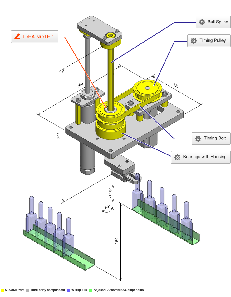
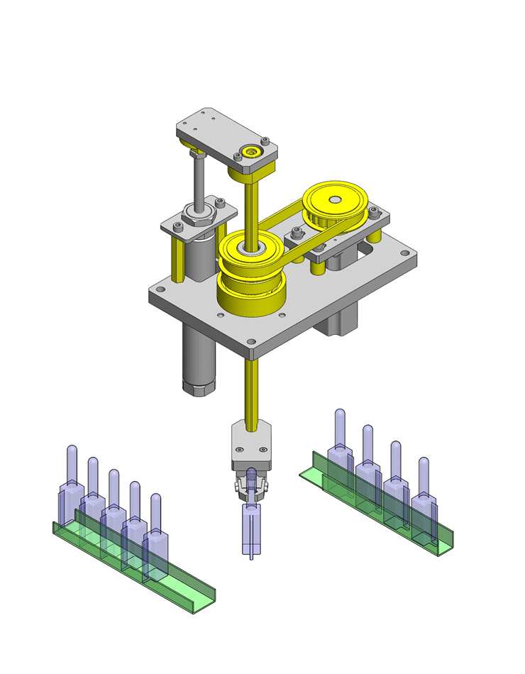
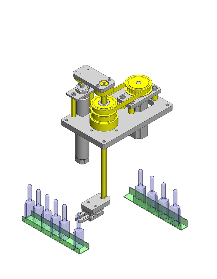
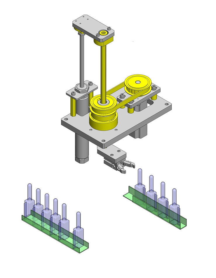
No.000032 Pick and Place Mechanism with Ball Spline
125
Compact design utilizing ball spline
Relevant category


Timing Belt
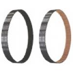
| Product name | Timing Belts - MXL / XL / L / H |
|---|---|
| Part number | TUN165L050 |
| Features | General purpose timing belts for transmission. Although some tooth fabrics for MXL and XL rubber belts are changed to comply with the bear-back specifications, it does not affect the performance. |
Selection criteria
Transmit torque from driving to driven pulley.
Risk info.
A pulley layout enabling replacements
Available sizes
■Timing Belts - MXL / XL / L / H
| Material | MXL | XL | L | H | ||
|---|---|---|---|---|---|---|
| Tooth surface cover | Tooth rubber | Core wire | ||||
| Nylon canvas | Chloroprene Rubber | Glass fiber cord S/Z Alternately Twisted Continuous | ○ | ○ | ○ | ○ |
| Polyurethane | Polyurethane | MXL: Kevlar XL・L: Steel cord | ○ | ○ | ○ | - |
■Reference dimensions
| Belt type | Pitch | Belt width | Belt length reference |
|---|---|---|---|
| MXL | 2.032 | 4.8, 6.4, 9.5, 12.7 | 100-1100 |
| XL | 5.08 | 6.4, 7.9, 9.5, 12.7 | 200-2100 |
| L | 9.525 | 12.7, 19.1, 25.4, 38.1 | 300-1800 |
| H | 12.7 | 19.1, 25.4, 38.1, 50.8 | 600-4300 |
Selection steps
■Timing belt selection procedure
* Timing belt selection is made together with timing pulley
Automated selection tool is available to use.
http://fawos.misumi.jp/FA_WEB/pulley_us/
- Determining of usage conditions
- Designed power・Rotational speed・Interim shaft distance・motion pattern, etc.
↓
- Belt (pulley) interim selection
- Belt type·Belt width
↓
- Verifying specification compatibility
-
- Verifying calculated shaft distance, etc.
- Verifying tension and load
Performance info.
■Load info. of timing belt
| Belt type | Small pulley rotational speed(rpm) | Designed power(kW) |
|---|---|---|
| MXL、XL、L、H、T5、T10 | 10-20000 | 0.01-800 |
Technical calculations
■Technical calculations

Timing Pulley
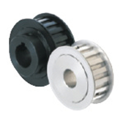
| Product name | Timing Pulleys L Type |
|---|---|
| Part number | ATPA19L050-A-N30 |
| Features | New! METRIC/ INCH Bores Available! |
Selection criteria
Transfer rotary motion. Aluminum type selected for weight reduction purposes.
Risk info.
Accuracy degradation due to wear over time.
Available sizes
■Timing Pulleys L Type
| Material | Surface treatment | Tooth type/Belt width | ||||||||||||||||
|---|---|---|---|---|---|---|---|---|---|---|---|---|---|---|---|---|---|---|
| MXL | XL | L | H | |||||||||||||||
| Pulley | Flange | 4.8 | 6.4 | 9.5 | 12.7 | 6.4 | 7.9 | 9.5 | 12.7 | 12.7 | 19.1 | 25.4 | 38.1 | 19.1 | 25.4 | 38.1 | 50.8 | |
| MXL、XL: 2017 Aluminum Alloy L、H: 7075 Aluminum Alloy | 5052 Aluminum Alloy | Clear anodize | ○ | ○ | ○ | ○ | ○ | ○ | ○ | ○ | ○ | ○ | ○ | ○ | ○ | ○ | ○ | ○ |
| Black anodize | ○ | ○ | ○ | ○ | ○ | ○ | ○ | ○ | ○ | ○ | ○ | ○ | ○ | ○ | ○ | ○ | ||
| Hard anodize | ○ | ○ | ○ | ○ | ○ | ○ | ○ | ○ | ○ | ○ | ○ | ○ | ○ | ○ | ○ | ○ | ||
| Electroless nickel plating | ○ | ○ | ○ | ○ | ○ | ○ | ○ | ○ | ○ | ○ | ○ | ○ | ○ | ○ | ○ | ○ | ||
| 1045 Carbon Steel | Low Carbon Steel | − | - | ○ | ○ | - | ○ | - | ○ | ○ | ○ | ○ | ○ | ○ | ○ | ○ | ○ | ○ |
| Black oxide | - | ○ | ○ | - | ○ | - | ○ | ○ | ○ | ○ | ○ | ○ | ○ | ○ | ○ | ○ | ||
| Electroless nickel plating | - | ○ | ○ | - | ○ | - | ○ | ○ | ○ | ○ | ○ | ○ | ○ | ○ | ○ | ○ | ||
| 304 Stainless Steel | 304 Stainless Steel | - | - | ○ | ○ | - | ○ | - | ○ | ○ | - | - | - | - | - | - | - | - |
■Pulley number of teeth and shaft bore DIA.
| Belt type | Shape | Number of teeth | Pitch circle DIA. | Shaft bore DIA. |
|---|---|---|---|---|
| MXL | K, A, B | 14-72 | φ9.6-46.57 | φ3-35 |
| XL | A, B | 10-72 | φ16.17-116.43 | φ4-80 |
| L | A, B, D | 10-72 | φ30.32-218.30 | φ6-100 |
| H | A, B, D | 14-72 | φ58.60-291.06 | φ12-100 |
K: With collar
A: No hub
B: With hub
D: With hub Relieved
Selection steps
■Timing pulley selection steps
* Timing pulley selection is made at the same time as the timing belt.
Automated selection tool is available to use.
http://fawos.misumi.jp/FA_WEB/pulley_us/
- Determining of usage conditions
- Design power・Rotational speed・Rotation ratio・Interim shaft distance, Motion pattern, etc.
↓
- Temporary selection of pulley (Belt)
- Tooth profile・Belt width
↓
- Verifying specification compatibility
-
- Verifying calculated shaft distance, etc.
- Verifying tension·Load
Accuracy Info
■Timing pulley accuracy
Shaft bore tolerance: H7
Technical calculations
■Technical calculations

Bearings with Housing

| Product name | Bearings with Housings - Standard Length, Double Bearings, Retained |
|---|---|
| Part number | BGRBB6007ZZ-50 |
Selection criteria
Compact double bearing type with high bearing performance
Available sizes
■Bearings with Housings - Standard Length, Double Bearings, Retained
| Flange Shape | Material | Surface treatment | ||
|---|---|---|---|---|
| Bearing | Housing | Retaining ring | Housing | |
| Round type Square type Compact type | Steel | 1045 Carbon Steel | Spring steel | Black oxide |
| 304 Stainless Steel | Electroless nickel plating | |||
| 2017 Aluminum Alloy | 304 Stainless Steel | Clear anodizing | ||
| Stainless | ||||
| 304 Stainless Steel | − | |||
■Sizes
| Shaft bore DIA. | Bearing part number | Seal | Overall length | Pilot O.D. | |
|---|---|---|---|---|---|
| φ30 | 6806 | Double shielded Non-contact rubber seal Contacting rubber seal | 35 | 50 | φ50 |
| 6906 | 35 | 50 | φ54 | ||
| 6006 | 40 | 60 | φ62 | ||
| 6206 | 50 | 60 | φ70 | ||
| φ35 | 6007 | 50 | 60 | φ70 | |
| 6207 | 60 | 80 | φ84 | ||
| φ40 | 6008 | 60 | 70 | φ78 | |
| 6208 | 60 | 80 | φ92 | ||
Accuracy Info
■Accuracy of bearing housing
Pilot O.D. tolerance: g7
Seating face - Pilot perpendicularity: 0.01

Ball Spline
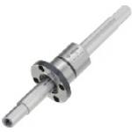
| Product name | Ball Splines -Both Ends Stepped Tapped |
|---|---|
| Part number | BSLM13-350-F6-E25-P10-Q10-M6-N6-SC0 |
Selection criteria
Suitable for a transmission element when linear and rotary motion are needed at the same time.
Available sizes
■Ball Splines -Both Ends Stepped Tapped
| Spline Shaft | Material | 52100 Bearing Steel | 440C Stainless Steel | |
|---|---|---|---|---|
| Hardness | 58HRC~ | 55HRC~ | ||
| Nut | Material | 4115 Alloy Steel | 440C Stainless Steel | |
| Hardness | 58HRC~ | 55HRC~ | ||
| Shape | Round flange | ○ | ○ | |
| Compact flange | ○ | - | ||
| Straight | ○ | ○ | ||
■Dimensions
| Spline shaft | Nut | ||
|---|---|---|---|
| Name No. | Shaft DIA. | Overall length | Pilot DIA. |
| 10 | φ10.4 | 60-600 | φ21 |
| 13 | φ13.4 | 60-600 | φ24 |
| 16 | φ16.6 | 70-600 | φ31 |
For 440C Stainless Steel spline shaft max. overall length is 390mm.
Selection steps
■Ball spline selection steps
- Determine application conditions
- (Load, Torque, Feed distance, Life)
↓
- Temporarily select ball spline specifications
- (Temporarily select spline shaft DIA., spline shaft length, overall length based on app. conditions)
↓
- Verify basic safety
-
- Allowable load
- Life
Accuracy Info
■Accuracy of ball spline shaft
(μm)
| Name No. | Spline Shaft DIA. | Nut O.D. runout | Spline shaft center runout(Max.) | |||||
|---|---|---|---|---|---|---|---|---|
| (Max.) | Length | -200 | 201-315 | 316-400 | 401-500 | 501- | ||
| 10 | φ10.4 | 33 | 59 | 83 | 103 | 82 | 102 | |
| 13 | φ13.4 | 39 | 56 | 71 | 83 | 62 | 75 | |
| 16 | φ16.6 | |||||||
Performance info.
■Ball spline load rating
| Name No. | Basic torque rating | Basic load rating | ||
|---|---|---|---|---|
| Dynamic (Nm) | Static (Nm) | Dynamic (kN) | Static (kN) | |
| 10 | 11 | 21 | 2.4 | 4.3 |
| 13 | 20 | 37 | 3.3 | 5.9 |
| 16 | 51 | 93 | 6.2 | 11.1 |
Technical calculations
Ball spline running life is calculated with the formula below.
●In case of radial loads
●In case of torque loads
- L: Life (km)
- ft: Temp. factor
- fh: Hardness factor
- fp: Load rating ratio
- fw: Load factor
- L0: Rated life (50km)
- C: Basic dynamic load rating (N)
- F: Applicable radial load (N)
- Ct: Basic dynamic torque rating (N・m)
- T: Applicable torque (N・m)
Ball spline life time is calculated with the formula below.
- Lh: Run hours (hr)
- L: Life (km)
- St: Stroke length
- n: Number of cycles per minute (cpm)
■Temp. factor (ft)

■Hardness factor (fh)
■Load rating ratio (fp)
| Name No. | Spline shaft DIA. | Distributed load | Direct download |
|---|---|---|---|
| 10 | φ10.4 | 1 | 0.71 |
| 13 | φ13.4 | 1 | 0.71 |
| 16 | φ16.6 | 1 | 0.68 |
■Load factor (fw)
| Application conditions | Load factor (fw) |
|---|---|
| No vibration or shocks (Low speed 1~2 15m/min or less) | 1-2 |
| Some vibrations and shocks (Med. speed 2~3 60m/min) | 2-3 |
| Severe vibrations and shocks (High speed 3 and over 60m/min or over) | 3- |

IDEA NOTE Transmit rotational power to the ball spline nut
This app. example uses a ball splines with flanged type nut.
Flanged nut is mounted on a hollow shaft, and rotation is transmitted via a pulley.


-

-
 Terms of use of CAD data and simplified drawing data
- These terms and conditions (hereinafter referred to as “the Terms") set forth the conditions for downloading CAD data and simplified drawing data posted on https://th.misumi-ec.com/ (hereinafter referred to as the "Website") operated by MISUMI (THAILAND) CO., LTD. (hereinafter referred to as "MISUMI"). By downloading CAD data and simplified drawing data posted on the Website (hereafter referred to as “Data”), customers are deemed to have agreed to these Terms.
- 1. Purpose of Use
-
MISUMI offers the following:
1)CAD data found on the Website (3D CAD data, 3D Intermediate data and 2D CAD data) for the purpose of informing customers of the characteristics of the products offered by MISUMI or a manufacturer affiliated with MISUMI for use in their designs.
2)Simplified drawing data (in PDF format) for the purpose of checking the specifications of products. - 2. Characteristics of Data
- There may be a discrepancy in certain characteristics of products (for example: tolerance, surface roughness, chamfer, etc.) between the Data and the actual product. Furthermore, for the purpose of reducing the file size of the Data, some information such as oil groove shapes, threads, or spring shapes, may be removed from the Data.
- 3. Disclaimer
- MISUMI carefully creates the Data but makes no warranty as to the accuracy of the Data. MISUMI may at any time, and with no prior notice to customers, revise or delete Data. MISUMI assumes no responsibility for any damage or loss resulting from any revision or deletion of the Data, or any errors in said data. Customers are solely responsible for all aspects of their own designs, including those made using MISUMI’s CAD data. MISUMI may provide customers with design example data on the Website, but the quality, accuracy, functionality, safety, reliability, etc., of such data are not guaranteed. MISUMI may, at any time, and in its sole discretion, request that the customer cease its use of or destroy the Data in its possession. MISUMI may request the customer provide MISUMI documentation of such destruction.
- 4.Prohibited Acts
-
Customers or users of the Data, are prohibited from the following acts regarding the Data, in whole or in part:
(1)Requesting quotations or placing orders for products with third parties other than those authorized by MISUMI or its affiliates;
(2)Receiving quotations or orders for products from third parties by providing the Data to a third party or using the Data in their own business;
(3)Displaying links to the Website related to the Data on their own websites, etc., without MISUMI's consent;
(4)Using or reproducing the Data beyond the scope of the above-stated Purpose of Use;
(5)Modifying, altering, tampering with, translating, or adapting the Data;
(6)Selling, transferring, lending, sublicensing, or providing the Data to third parties in any way without MISUMI’s consent;
(7)Altering the content, reverse engineering, decompiling, disassembling, or analyzing the Data;
(8)Publicly disclosing or exhibiting the Data without MISUMI's consent;
(9)Using the Data for the purpose of providing products and services identical or similar to those of MISUMI;
(10)Performing acts that interfere with the proper functioning of this Website, such as acquiring Data in bulk. - 5. Copyright
-
All title and copyright in and to any information contained in the Data are owned by MISUMI or the relevant manufacturer affiliated with MISUMI and are protected by applicable copyright laws and international treaties. By downloading Data, the customer acquires no ownership rights of any kind in the intellectual property contained within. Without prior approval from MISUMI, no part of the Data may be utilized (reproduced, modified, reverse-engineered, uploaded, presented, sent, distributed, licensed, sold, or published) for any purpose other than that mentioned above.
In the event Data is found to have been to be used for any purpose other than that mentioned above or against any applicable laws, MISUMI may pursue any legal remedy available to it, which may result in forbidding the offending user from using the Data or accessing the Website. - 6. Third-Party Data
- MISUMI offers some Data provided by third parties. Such Data may be subject to separate terms and conditions, in addition to these terms. MISUMI makes no guarantee or warranty regarding Data from third parties.
- 7. Export Control
- Customers shall comply with all applicable laws and regulations regarding the export of the Data.
- 8. Amendments to the Terms
- MISUMI may, at any time, and in its sole discretion, modify these terms and conditions; any such modification will be effective immediately.
- 9. Severability
- If any term or provision of these Terms is invalid, illegal, or unenforceable in any jurisdiction, such invalidity, illegality, or unenforceability shall not affect any other term or provision of these Terms or invalidate or render unenforceable such term or provision in any other jurisdiction.
- 10.Miscellaneous
- These Terms and any disputes arising in connection therewith shall be exclusively governed by and construed in accordance with the laws of Thailand, without regard to its conflicts of law principles. The authorized courts in Thailand shall have exclusive jurisdiction to adjudicate any dispute arising in connection with these Terms.
- Revised: 16th November, 2025
CAD Download (Unit Assembly)
CAD Download: File Format
CAD Data Limitations
-
Assembly data shows the assembly drawings in the concept design phase. The sole purpose of the data is to explain the structure and functionality of the assembly and is not considered nor to be used as a final design.
You will need to edit the Data so that it meets your specific design conditions. -
Unit assembly Data consists of some sub-assemblies.
It is configured so that each sub-assembly unit can be used as it is or edited. - The Data for fabricated parts is based on easy-to-edit dimensions and shapes in sketches and histories.
- The Data including the third-part components are made by the Company.
* The part in the frame is a sub-assembly unit.
-

- * Unit assembly Data consists of some sub-assemblies.
It is configured so that each sub-assembly unit can be used as it is or edited.
Application Overview
Purpose
- Pick, rotate and lower workpiece to next work station.
Target workpiece
- Plastic pin with square base
- Pin DIA.: φ15, Length: 100mm
- Protrusion on one location
Design Specifications
Operating Conditions or Design Requirements
- W150XD240XH377mm
- Up/down stroke: 150mm
- Rotation angle: 90deg.
Required Performance
- Rotational position accuracy: ±1°
Selection Criteria for Main Components
- A ball spline is used for accurate linear motion as well as for its ability to rotate its orientation.
Design Evaluation
Verification of main components
- Select a motor that satisfies the torque at required speed.
- Motor selection
- Calculation of load torque
App. condition: Timing belt drive - Conditional value:
D = 57.61 x 10³m - pulley pitch diameter
F = 5N - belt tension force
W = 0kg - workpiece mass
μ = 0.1 - coefficient of friction, sliding surface
g = 9.8m/s² - gravitational acceleration - From: Load torque T = D/2 × (F + μWg) Nm
T = 1 / 2 × 57.61 × 10³ × (5 + 0.1 × 0 × 9.8) = 144 × 10³Nm
therefore, we select a motor with larger torque then T =0.14Nm - Torque of the selected motor MAMA012P1A (with continuous operation range up to 5000r/min) is 0.19Nm, and satisfy requirements.
Motor rated torque > Actually applied torque.
- Calculation of load torque
Other Design Consideration
- For smooth rotation ball spine is supported by ball bearing on two ends and rotation is transmitted thru pulley.
- If needed install position sensors.
Explore Similar Application Examples

-

-

-

-

-

-

-

-

-

-

-

-

-

-

-

-

-

-

Relevant category
-

-

-

-

-

-

-

-

-

-

-

-

-

-

-

-

-

-

-

-

-

-

-

-

-

-

-

-

-

-

-

-

-

-

-

-

-

-

Relevant category
-

-

-

-

-

-

-

-

-

-

-

-

-

-

-

-

-

-

-

-

-

-

-

-

-

-

-

-

-

-

-

-

-

-

-

-

-

-

-

-

-

-

-

-

-

-

-

-

-

-

-

-

-

-

-

-

-

-

-

-

-

-

-

-

-

-

-


Payment Methods
- Bank
-
- Prompt Pay
-


- Cash
-

- Cash on Delivery
Social Media
MISUMI Contact
Copyright © MISUMI Corporation All Rights Reserved.