(!) Since support from Microsoft will end on January 14 2020, Windows 7 user might not be able to use MISUMI website effectively. Please consider to update your system as ‘MISUMI Website system requirement’.


- inCAD Library Home
- > No.000289 Removal of Static Electricity from Large Workpieces
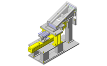
No.000289 Removal of Static Electricity from Large Workpieces
26
Parallel use of two single-axis actuators
Relevant category


Single Axis Actuator
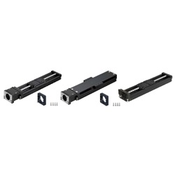
| Product name | Single Axis Actuators LX45 Standard / Cover Type |
|---|---|
| Part number | LX4510-B1-A4540-590 |
Selection criteria
Can feed workpieces at a constant velocity with speed adjustment capabilities.
Available sizes
■Single Axis Actuators LX45 Standard / Cover Type
| Nominal (height) (mm) | Lead (mm) | Effective Stroke (mm) |
|---|---|---|
| 15 | 2 | 26.9 |
| 51.9 | ||
| 76.9 | ||
| 101.9 | ||
| 126.9 | ||
| 151.9 | ||
| 20 | 1 5 | 16.5 |
| 36.5 | ||
| 86.5 | ||
| 136.5 | ||
| 186.5 | ||
| 236.5 | ||
| 26 | 2 5 10 | 17 |
| 67 | ||
| 117 | ||
| 167 | ||
| 217 | ||
| 267 | ||
| 317 | ||
| 30 | 5 10 | 29 |
| 54 | ||
| 104 | ||
| 154 | ||
| 204 | ||
| 254 | ||
| 304 | ||
| 354 | ||
| 404 | ||
| 454 | ||
| 504 | ||
| 45 | 10 20 | 210.4 |
| 260.4 | ||
| 310.4 | ||
| 360.4 | ||
| 410.4 | ||
| 460.4 |
Selection steps
■Selection Procedure for Single Axis Actuators
Load Capacity
↓
Stroke
↓
Cycle Time or Max. Speed
↓
Check for Details
Accuracy Info
■Accuracy of Single Axis Actuators
| Nominal (height) | Positioning Accuracy (mm) | Positioning Repeatability (mm) | ||
|---|---|---|---|---|
| High Grade | (Only nominal 30 is the high grade with total base length 450 or more.) | Precision Grade | (Only nominal 30 is the precision grade with total base length of 450 or more.) | |
| 15 | 0.04 | ― | 0.02 | ― |
| ±0.004 | ±0.003 | |||
| 20 | 0.06 | 0.02 | ||
| ±0.005 | ±0.003 | |||
| 26 | 0.06 | 0.02 | ||
| ±0.005 | ±0.003 | |||
| 30 | 0.06 | 0.1 | 0.02 | 0.025 |
| ±0.005 | ±0.005 | ±0.003 | ±0.003 | |
| 45 | 0.1 | ― | 0.025 | ― |
| ±0.005 | ±0.003 | |||
Performance info.
■Speeds / Loads (Load Info.) of Single Axis Actuators
| Nominal (height) (mm) | Lead (mm) | Load Rating | Allowable Moment (N·m) | Max. Velocity (mm/sec) | |||
|---|---|---|---|---|---|---|---|
| Basic Dynamic Rating (N) | Basic Static Rating (n) | Pitching | Yawing | Rolling | |||
| 15 | 2 | 2072 | 3701 | 13 | 13 | 41 | 330 |
| 20 | 1 | 3277 | 6199 | 27 | 27 | 93 | 190 |
| 5 | 694 | ||||||
| 26 | 2 | 6522 | 11871 | 70 | 70 | 225 | 290 |
| 5 | 521 | ||||||
| 10 | - | ||||||
| 30 | 5 | 9732 | 17218 | 126 | 126 | 387 | 410 |
| 10 | 830 | ||||||
| 45 | 10 | 18450 | 32441 | 291 | 291 | 972 | 550 |
| 20 | 1110 | ||||||

Couplings
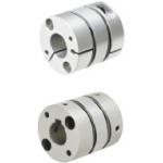
| Product name | Couplings - High Positioning Accuracy Disc, Clamping / Keyway |
|---|---|
| Part number | SCXW28-8-10 |
| Features | Used for High Precision Devices and Clean room environments. |
Selection criteria
Has high positioning accuracy compatible with servo.
Available sizes
■Couplings - High Positioning Accuracy Disc, Clamping / Keyway
| Material | Surface Treatment | ||||
|---|---|---|---|---|---|
| Main Body | Disc | Hex Screw | Main Body | Disc | Hex Screw |
| Aluminum Alloy | Stainless Steel | 4137 Alloy Steel | Anodized | - | Trivalent Chromate |
■Sizes and Dimensions
| O.D. | Shaft Bore Dia. (select drive / driven sides) | Overall Length | |||||||||||||
|---|---|---|---|---|---|---|---|---|---|---|---|---|---|---|---|
| φ4 | φ5 | φ6 | φ8 | φ10 | φ12 | φ14 | φ15 | φ17 | φ19 | φ20 | φ22 | φ24 | φ25 | ||
| φ21 | ○ | ○ | ○ | ○ | - | - | - | - | - | - | - | - | - | - | 24.5 |
| φ28 | - | - | ○ | ○ | ○ | ○ | - | - | - | - | - | - | - | - | 32 |
| φ34 | - | - | ○ | ○ | ○ | ○ | ○ | - | - | - | - | - | - | - | 35 |
| φ46 | - | - | - | ○ | ○ | ○ | ○ | ○ | ○ | ○ | - | - | - | - | 44 |
| φ55 | - | - | - | - | - | ○ | ○ | ○ | ○ | ○ | ○ | ○ | ○ | ○ | 55 |
Accuracy Info
■Accuracy of Coupling
| O.D. | Shaft Bore Tolerance | Allowable Angular Misalignment (°) | Lateral Misalignment (mm) |
|---|---|---|---|
| φ21 | H7 | 1.0 | 0.10 |
| φ28 | 1.2 | 0.15 | |
| φ34 | 1.5 | 0.20 | |
| φ46 | 0.25 | ||
| φ55 |
Performance info.
■Load of couplings
| O.D. | Allowable Torque (N・m) | Max. Rotational Speed (r/min) | Moment of Inertia (kg・m²) |
|---|---|---|---|
| φ21 | 1.2 | 10000 | 1.20×10 -6 |
| φ28 | 1.6 | 4.68×10 -6 | |
| φ34 | 4.0 | 1.10×10 -5 | |
| φ46 | 10.0 | 4.70×100 -5 | |
| φ55 | 25.0 | 1.19×100 -4 |


-

-
 Terms of use of CAD data and simplified drawing data
- These terms and conditions (hereinafter referred to as “the Terms") set forth the conditions for downloading CAD data and simplified drawing data posted on https://th.misumi-ec.com/ (hereinafter referred to as the "Website") operated by MISUMI (THAILAND) CO., LTD. (hereinafter referred to as "MISUMI"). By downloading CAD data and simplified drawing data posted on the Website (hereafter referred to as “Data”), customers are deemed to have agreed to these Terms.
- 1. Purpose of Use
-
MISUMI offers the following:
1)CAD data found on the Website (3D CAD data, 3D Intermediate data and 2D CAD data) for the purpose of informing customers of the characteristics of the products offered by MISUMI or a manufacturer affiliated with MISUMI for use in their designs.
2)Simplified drawing data (in PDF format) for the purpose of checking the specifications of products. - 2. Characteristics of Data
- There may be a discrepancy in certain characteristics of products (for example: tolerance, surface roughness, chamfer, etc.) between the Data and the actual product. Furthermore, for the purpose of reducing the file size of the Data, some information such as oil groove shapes, threads, or spring shapes, may be removed from the Data.
- 3. Disclaimer
- MISUMI carefully creates the Data but makes no warranty as to the accuracy of the Data. MISUMI may at any time, and with no prior notice to customers, revise or delete Data. MISUMI assumes no responsibility for any damage or loss resulting from any revision or deletion of the Data, or any errors in said data. Customers are solely responsible for all aspects of their own designs, including those made using MISUMI’s CAD data. MISUMI may provide customers with design example data on the Website, but the quality, accuracy, functionality, safety, reliability, etc., of such data are not guaranteed. MISUMI may, at any time, and in its sole discretion, request that the customer cease its use of or destroy the Data in its possession. MISUMI may request the customer provide MISUMI documentation of such destruction.
- 4.Prohibited Acts
-
Customers or users of the Data, are prohibited from the following acts regarding the Data, in whole or in part:
(1)Requesting quotations or placing orders for products with third parties other than those authorized by MISUMI or its affiliates;
(2)Receiving quotations or orders for products from third parties by providing the Data to a third party or using the Data in their own business;
(3)Displaying links to the Website related to the Data on their own websites, etc., without MISUMI's consent;
(4)Using or reproducing the Data beyond the scope of the above-stated Purpose of Use;
(5)Modifying, altering, tampering with, translating, or adapting the Data;
(6)Selling, transferring, lending, sublicensing, or providing the Data to third parties in any way without MISUMI’s consent;
(7)Altering the content, reverse engineering, decompiling, disassembling, or analyzing the Data;
(8)Publicly disclosing or exhibiting the Data without MISUMI's consent;
(9)Using the Data for the purpose of providing products and services identical or similar to those of MISUMI;
(10)Performing acts that interfere with the proper functioning of this Website, such as acquiring Data in bulk. - 5. Copyright
-
All title and copyright in and to any information contained in the Data are owned by MISUMI or the relevant manufacturer affiliated with MISUMI and are protected by applicable copyright laws and international treaties. By downloading Data, the customer acquires no ownership rights of any kind in the intellectual property contained within. Without prior approval from MISUMI, no part of the Data may be utilized (reproduced, modified, reverse-engineered, uploaded, presented, sent, distributed, licensed, sold, or published) for any purpose other than that mentioned above.
In the event Data is found to have been to be used for any purpose other than that mentioned above or against any applicable laws, MISUMI may pursue any legal remedy available to it, which may result in forbidding the offending user from using the Data or accessing the Website. - 6. Third-Party Data
- MISUMI offers some Data provided by third parties. Such Data may be subject to separate terms and conditions, in addition to these terms. MISUMI makes no guarantee or warranty regarding Data from third parties.
- 7. Export Control
- Customers shall comply with all applicable laws and regulations regarding the export of the Data.
- 8. Amendments to the Terms
- MISUMI may, at any time, and in its sole discretion, modify these terms and conditions; any such modification will be effective immediately.
- 9. Severability
- If any term or provision of these Terms is invalid, illegal, or unenforceable in any jurisdiction, such invalidity, illegality, or unenforceability shall not affect any other term or provision of these Terms or invalidate or render unenforceable such term or provision in any other jurisdiction.
- 10.Miscellaneous
- These Terms and any disputes arising in connection therewith shall be exclusively governed by and construed in accordance with the laws of Thailand, without regard to its conflicts of law principles. The authorized courts in Thailand shall have exclusive jurisdiction to adjudicate any dispute arising in connection with these Terms.
- Revised: 16th November, 2025
CAD Download (Unit Assembly)
CAD Download: File Format
CAD Data Limitations
-
Assembly data shows the assembly drawings in the concept design phase. The sole purpose of the data is to explain the structure and functionality of the assembly and is not considered nor to be used as a final design.
You will need to edit the Data so that it meets your specific design conditions. -
Unit assembly Data consists of some sub-assemblies.
It is configured so that each sub-assembly unit can be used as it is or edited. - The Data for fabricated parts is based on easy-to-edit dimensions and shapes in sketches and histories.
- The Data including the third-part components are made by the Company.
* The part in the frame is a sub-assembly unit.
-

- * Unit assembly Data consists of some sub-assemblies.
It is configured so that each sub-assembly unit can be used as it is or edited.
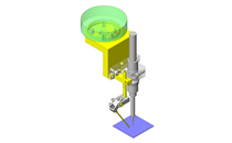
Application Overview
Purpose
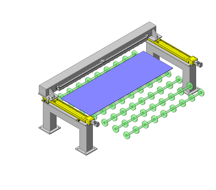
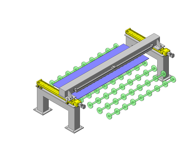
- A device to remove static electricity from resin material that is likely to create an electrical charge.
- Static electricity is removed after the workpiece is stopped.
Points for use
- Automatic horizontal movement enabled by single-axis actuators and servo motors.
Target workpiece
- Workpiece: electrically charged resin material.
- Dimensions: W430 x D1200 x t5mm
- Mass: 3.4kg
Design Specifications
Operating Conditions or Design Requirements
- Operational Specifications
- Action stroke: 430mm
- Feed speed: 45mm/sec
- Dimensions
- Outer dimensions: W1616 x D812 x H515mm
Selection Criteria for Main Components
- Capacity of single-axis actuator.
Design Evaluation
Verification of main components
- The actuator capacity is verified based on the load condition.
- Capacity of single-axis actuator.
-
- Conditional value: stroke Ls = 430mm, feed speed V = 45mm, number of rpms n1 = 2rpm, load factor fw = 1.2 (when AC servo motor is used), operation condition "at low speed (250mm/sec (15m/min) or less)," beam [mass [kg], distances from linear block to the centers of gravity of X, Y, and Z [mm]] = [9.81, 80.18, 750, 50.17], ionizer [mass [kg], distances from linear block to centers of gravity of X, Y, and Z [mm]] = [0.73, 16.88, 750, 42.66]
→ Service life of rail part: 7 [years] * Calculated using Misumi EC Calculation Software.
→ Converted into service period assuming it is used 8 hours a day: 21 [years]
- Conditional value: stroke Ls = 430mm, feed speed V = 45mm, number of rpms n1 = 2rpm, load factor fw = 1.2 (when AC servo motor is used), operation condition "at low speed (250mm/sec (15m/min) or less)," beam [mass [kg], distances from linear block to the centers of gravity of X, Y, and Z [mm]] = [9.81, 80.18, 750, 50.17], ionizer [mass [kg], distances from linear block to centers of gravity of X, Y, and Z [mm]] = [0.73, 16.88, 750, 42.66]
Other Design Consideration
- Due to the large moment load of the removal device, two single-axis actuators are used in parallel.
- Feed mechanism are controlled by servo motors.
- To achieve synchronization, a sequencer and servo amplifier are utilized.
- Calculate the required spacing between the ionizer and the workpiece during the design stage.
- The three photo sensors mounted on the main frame detect overruns at the origin position and both ends.
Explore Similar Application Examples

-

-

-

-
-

-

-

-

-

-

-
-

-

-

-

-

-

-

-

-

-

-

-

-

-

-

-

Relevant category
-

-

-

-

-

-

-

-

-

-

-

-

-

-

-

-

-

-

-

-

-

-

-

-

-

-

-

-

-

-

-

-

-

-

-

-

-

-

-

-

-

-

-

-

-

-

-

-


Payment Methods
- Bank
-
- Prompt Pay
-


- Cash
-

- Cash on Delivery
Social Media
MISUMI Contact
Copyright © MISUMI Corporation All Rights Reserved.