(!) Since support from Microsoft will end on January 14 2020, Windows 7 user might not be able to use MISUMI website effectively. Please consider to update your system as ‘MISUMI Website system requirement’.


- inCAD Library Home
- > No.000035 Cylinder Linear Motion Mechanism
No.000035 Cylinder Linear Motion Mechanism
111
Table slide with stroke end adjustment
Relevant category


Shock Absorber
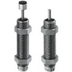
| Product name | Shock Absorbers |
|---|---|
| Part number | MAKC0805B |
Selection criteria
To smooth out shock and absorb energy at end stroke.
Available sizes
■Shock Absorbers (Fixed)
| Type | Thread Dia. - Pitch | Stroke | Body material | Surface treatment | Speed | Overall length | |
|---|---|---|---|---|---|---|---|
| With Cap | Without Cap | ||||||
| With Cap Without Cap | M4-0.5 | 4 | 303 Stainless Steel | - | Low Speed | 32.6 | 28.6 |
| M6-0.75 | Low Speed | 33 | 29 | ||||
| M8-0.75 | 5 | C36000 Brass | Electroless Nickel Plating | Low Speed | 37 | 32 | |
| M10-1 | Carbon Steel | Low Speed | 39 | ||||
| 8 | Low Speed | 53 | 46 | ||||
| Low Speed | 55 | 48 | |||||
| Medium Speed | |||||||
| High Speed | |||||||
Selection steps
■Shock Absorbers Selection Steps
1. Calculate the inertia energy (E1)
Calculate the energy based on the collision material mass (m), collision velocity (V), moment of inertia (I), and collision angle velocity (u), according to the selection calculation example.
↓
2. Temporarily select the absorber stroke
Determine the temporary stroke (S') according to Fig.1.
↓
3. Calculate the addition energy (E2')
Verify the existence of thrust force (F) and calculate the addition energy according to the selection calculation example.
↓
4. Calculate the total energy
Calculate the total energy by adding inertia energy (E1) and addition energy (E2') together.
↓
Fig.1 Determine the temporary stroke (S') based on the inertia energy (E1) (adjustable / fixed type)

5. Check the equivalent mass
Calculate the equivalent mass according to the selection calculation example to check if it is less than or equal to the maximum equivalent mass (me') shown in the catalog.
↓
6. Select the absorption property structure from the energy ratio.
Temporarily select the orifice type according to Fig.2.
↓
7. Check the max. absorption energy per minute
Calculate the energy per minute (ET) based on the operating cycle (times/min) and the total energy to confirm that it is within the operating range.
Fig.2 Select the orifice type based on the energy ratio (addition energy (E2') / inertia energy (E1))

Performance info.
■Shock Absorber Properties (Fixed)
| Thread Dia. - Pitch | Stroke | Speed | Max. Absorption Energy | Max. Equivalent Mass(kg) | |
|---|---|---|---|---|---|
| Each Time(J) | Per Minute(J) | ||||
| M4-0.5 | 4 | A | 0.1 | 4.5 | 1 |
| B | 0.3 | 13.5 | 3 | ||
| M6-0.75 | A | 0.1 | 4.5 | 1 | |
| B | 0.3 | 13.5 | 2 | ||
| L | 0.5 | 22.5 | 3 | ||
| M8-0.75 | 5 | A | 0.39 | 17.6 | |
| B | 0.68 | 22.5 | 5 | ||
| M10-1 | A | 41.1 | |||
| B | 0.98 | 8 | |||
| 8 | A | 58.8 | 7 | ||
| B | 1.47 | 10 | |||
| L | 2.94 | 20 | |||
| M | 9 | ||||
| H | 2.5 | ||||
| Speed Type | Impact Speed Range | |
|---|---|---|
| Low Speed | A | 0.3-1m/s |
| B | ||
| L | ||
| Medium Speed | M | 0.3-2m/s |
| High Speed | H | 0.3-3m/s |
Technical calculations
- ■Shock Absorber Energy Calculations
- Selection example: Horizontal collision with air cylinder thrust
-
- m=30kg
- V=0.6m/s
- N = 20 times/min
- Air Cylinder
- I.D.: φ40, Operating pressure: 0.5 Mpa
-
●Inertia energy E1 (J)
-
●Temporary stroke S' (mm)
S' = 15 mm according to Fig.1
(See the shock absorber selection steps for Fig.1) -
●Addition energy E2' (J)
Cylinder thrust is F = 628.4 N
E2' = F x S' = 628.4 x 0.015 = 9.4 J -
●Total energy E' (J)
E' = E1 + E2' = 5.4 + 9.4 = 14.8J
-
Equivalent mass me' (kg)
-
Temporary selection
Select the adjustable type
Select the medium speed M from the collision velocity
Select MAC2016M from E' and me' (stroke S = 16 mm) -
Re-calculate
E2=F×S=10.1J
E=E1+E2=15.5J
Energy per minute ET
ET=E×N=15.5J×20=310J/min

Adjusting Stopper Screw

| Product name | Adjusting Stopper Screws- Hexagon Socket, L Configurable, Fine Thread |
|---|---|
| Part number | ANB6-30 |
Selection criteria
Forward End Position Fine Adjustment
Risk info.
Contact Surface Abrasion
Available sizes
■Adjusting Stopper Screws (Hexagon Socket Type, L selectable) Spherical Tip
| Screw Type | Material | Hardness (Tip) | Surface treatment | Accessory(Nut x 1 pc.) | |
|---|---|---|---|---|---|
| Material | Surface treatment | ||||
| Fine Thread ・ Coarse Thread | 1045 Carbon Steel | 45〜50HRC | Electroless Nickel Plating | 1018 Carbon Steel | Trivalent Chromate |
| Trivalent Chromate | |||||
| 4137 Alloy Steel | 50HRC〜 | ||||
| 304 Stainless Steel | − | − | 304 Stainless Steel | − | |
| 420 Stainless Steel | 45HRC〜 | − | |||
■Size Specification
| Thread Diameter x Pitch | Overall length (in the increment of 5mm) | |
|---|---|---|
| Fine Thread | Coarse Thread | |
| M3×0.35 | M3×0.5 | 10~40 |
| M4×0.5 | M4×0.7 | 10~60 |
| M5×0.5 | M5×0.8 | 10~60 |
| M6×0.75 | M6×1.0 | 15~60 |
| M8×0.75 | M8×1.25 | 20~60 |
| M10×1.0 | M10×1.5 | 25~100 |
| M12×1.0 | M12×1.75 | 30~100 |
| M16×1.5 | M16×2.0 | 40~100 |
| M20×1.5 | M20×2.5 | 45~120 |
* Selectable size will differ depending on materials.
* For details, please see products page.

Floating Joint
| Product name | Floating Joints - Quick Connection Type - Cylinder Connector and Holder Set |
|---|---|
| Part number | FJRHA5-0.8 |
Selection criteria
A more rigid type was selected to support the load applied to cylinder.
Available sizes
■Floating Joints - Quick Connection Type
| Part No. | Part name | Material |
|---|---|---|
| ① | Stud | 304 Stainless Steel |
| ② | Nut | 1018 Carbon Steel |
| ③ | Case | C36000 Brass |
| ④ | Ball Holder | |
| ⑤ | Ball Joiner | |
| ⑥ | Socket | |
| ⑦ | Rod Tip Nut | SWCH8R Carbon Wire Steel (JIS) |

| Screw Diameter-Pitch | Stud Length | Screw Depth | Overall length |
|---|---|---|---|
| M4−0.7 | 10 | 4.5 | 26 |
| M5−0.8 | 12.5 | 6 | 33.5 |
| M6−1.0 | 15.5 | 36.5 |

-
 Terms of use of CAD data and simplified drawing data
- These terms and conditions (hereinafter referred to as “the Terms") set forth the conditions for downloading CAD data and simplified drawing data posted on https://th.misumi-ec.com/ (hereinafter referred to as the "Website") operated by MISUMI (THAILAND) CO., LTD. (hereinafter referred to as "MISUMI"). By downloading CAD data and simplified drawing data posted on the Website (hereafter referred to as “Data”), customers are deemed to have agreed to these Terms.
- 1. Purpose of Use
-
MISUMI offers the following:
1)CAD data found on the Website (3D CAD data, 3D Intermediate data and 2D CAD data) for the purpose of informing customers of the characteristics of the products offered by MISUMI or a manufacturer affiliated with MISUMI for use in their designs.
2)Simplified drawing data (in PDF format) for the purpose of checking the specifications of products. - 2. Characteristics of Data
- There may be a discrepancy in certain characteristics of products (for example: tolerance, surface roughness, chamfer, etc.) between the Data and the actual product. Furthermore, for the purpose of reducing the file size of the Data, some information such as oil groove shapes, threads, or spring shapes, may be removed from the Data.
- 3. Disclaimer
- MISUMI carefully creates the Data but makes no warranty as to the accuracy of the Data. MISUMI may at any time, and with no prior notice to customers, revise or delete Data. MISUMI assumes no responsibility for any damage or loss resulting from any revision or deletion of the Data, or any errors in said data. Customers are solely responsible for all aspects of their own designs, including those made using MISUMI’s CAD data. MISUMI may provide customers with design example data on the Website, but the quality, accuracy, functionality, safety, reliability, etc., of such data are not guaranteed. MISUMI may, at any time, and in its sole discretion, request that the customer cease its use of or destroy the Data in its possession. MISUMI may request the customer provide MISUMI documentation of such destruction.
- 4.Prohibited Acts
-
Customers or users of the Data, are prohibited from the following acts regarding the Data, in whole or in part:
(1)Requesting quotations or placing orders for products with third parties other than those authorized by MISUMI or its affiliates;
(2)Receiving quotations or orders for products from third parties by providing the Data to a third party or using the Data in their own business;
(3)Displaying links to the Website related to the Data on their own websites, etc., without MISUMI's consent;
(4)Using or reproducing the Data beyond the scope of the above-stated Purpose of Use;
(5)Modifying, altering, tampering with, translating, or adapting the Data;
(6)Selling, transferring, lending, sublicensing, or providing the Data to third parties in any way without MISUMI’s consent;
(7)Altering the content, reverse engineering, decompiling, disassembling, or analyzing the Data;
(8)Publicly disclosing or exhibiting the Data without MISUMI's consent;
(9)Using the Data for the purpose of providing products and services identical or similar to those of MISUMI;
(10)Performing acts that interfere with the proper functioning of this Website, such as acquiring Data in bulk. - 5. Copyright
-
All title and copyright in and to any information contained in the Data are owned by MISUMI or the relevant manufacturer affiliated with MISUMI and are protected by applicable copyright laws and international treaties. By downloading Data, the customer acquires no ownership rights of any kind in the intellectual property contained within. Without prior approval from MISUMI, no part of the Data may be utilized (reproduced, modified, reverse-engineered, uploaded, presented, sent, distributed, licensed, sold, or published) for any purpose other than that mentioned above.
In the event Data is found to have been to be used for any purpose other than that mentioned above or against any applicable laws, MISUMI may pursue any legal remedy available to it, which may result in forbidding the offending user from using the Data or accessing the Website. - 6. Third-Party Data
- MISUMI offers some Data provided by third parties. Such Data may be subject to separate terms and conditions, in addition to these terms. MISUMI makes no guarantee or warranty regarding Data from third parties.
- 7. Export Control
- Customers shall comply with all applicable laws and regulations regarding the export of the Data.
- 8. Amendments to the Terms
- MISUMI may, at any time, and in its sole discretion, modify these terms and conditions; any such modification will be effective immediately.
- 9. Severability
- If any term or provision of these Terms is invalid, illegal, or unenforceable in any jurisdiction, such invalidity, illegality, or unenforceability shall not affect any other term or provision of these Terms or invalidate or render unenforceable such term or provision in any other jurisdiction.
- 10.Miscellaneous
- These Terms and any disputes arising in connection therewith shall be exclusively governed by and construed in accordance with the laws of Thailand, without regard to its conflicts of law principles. The authorized courts in Thailand shall have exclusive jurisdiction to adjudicate any dispute arising in connection with these Terms.
- Revised: 16th November, 2025
CAD Download (Unit Assembly)
CAD Download: File Format
CAD Data Limitations
-
Assembly data shows the assembly drawings in the concept design phase. The sole purpose of the data is to explain the structure and functionality of the assembly and is not considered nor to be used as a final design.
You will need to edit the Data so that it meets your specific design conditions. -
Unit assembly Data consists of some sub-assemblies.
It is configured so that each sub-assembly unit can be used as it is or edited. - The Data for fabricated parts is based on easy-to-edit dimensions and shapes in sketches and histories.
- The Data including the third-part components are made by the Company.
* The part in the frame is a sub-assembly unit.
-

- * Unit assembly Data consists of some sub-assemblies.
It is configured so that each sub-assembly unit can be used as it is or edited.
Application Overview
Purpose
- Cylinder driven table.
Target workpiece
- Small printed circuit boards.
- W40 x D110 x H1.6 mm
Design Specifications
Operating Conditions or Design Requirements
- External dims.; W120 x D564 x H45mm
- Transfer stroke: 200mm
Required Performance
- Positioning accuracy: ±0.5 /200mm
- Load: Table + Workpiece = 0.2kg
Selection Criteria for Main Components
- Select a cylinder with ample thrust for transfer.
Design Evaluation
Verification of main components
- Select cylinder bore based on work load.
- Selection of cylinder bore
- Operating conditions:
Horizontal mount
M = 0.3kg - Load mass (Workpiece, Block)
μ = 0.06 - Coefficient of friction
g = 9.8m/s² - Gravitational acceleration
P = 0.4MPa - Operating pressure
η=50 % - Load factor
Actual load F = μMg,
therefore F = 0.006 × 0.3 × 9.8 = 0.02N
Required cylinder force F0 = (F / η) × 100 ,
thus F0 = (0.02 / 50) × 100 = 0.04N
Cylinder Bore Dia. is determined based on cylinder force, F0 = A x P
Where A (mm²) - cylinder pressure area
DO=√(1.274 × F0 / P) therefore DO=√(1.274 × 0.04 / 0.4) = 3.6mm
Cylinder bore dia.: 16mm is selected
Cylinder tube I.D. DO=√(1.274 × F0 / P) therefore DO=√(1.274 × 0.04 / 0.4) = 3.6mm
Cylinder tube I.D.: 16mm is selected
- Operating conditions:
Other Design Consideration
- Shock absorbers are installed on fore/aft stroke ends to avoid impact stops.
- Stopper is located at the load center.
Explore Similar Application Examples

-

-

-

-

-

-

-

-

-

-

-

-

-

-

-

-

-

-

Relevant category
-

-

-

-

-

-

-

-

-

-

-

-

-

-

-

-

-

-

-

-

-

-

-

-

-

-

-

-

-

-

-

-

-

-

-

-

-

-

Relevant category
-

-

-

-

-

-

-

-

-

-

-

-

-

-

-

-

-

-

-

-

-

-

-

-

-

-

-

-

-

-

-

-

-

-

-

-

-

-

-

-

-

-

-

-

-

-

-

-

-

-

-

-

-

-

-

-

-

-

-

-

-

-

-

-

-

-

-


Payment Methods
- Bank
-
- Prompt Pay
-


- Cash
-

- Cash on Delivery
Social Media
MISUMI Contact
Copyright © MISUMI Corporation All Rights Reserved.