Linear guide
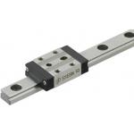
| Product name | Miniature Linear Guides - Standard Block with Dowel Holes? |
| Part number | SSE2BNZ13-145 |
| Features | Dowel Hole facilitates positioning of Parts Mounted on Blocks |
* Orange colored cells in the table below indicate the part numbers used in this example.
Selection criteria
Effective as a linear motion system to move the table up/down by diagonally mounting.
Back to page top
Available sizes
■Miniature linear guide (Standard block with dowel holes, Slight clearance, Standard grade)
| Material | Hardness |
| 440C Stainless Steel | 56HRC- |
| Carbon steel | 58HRC- |
■Sizes and Dimensions
| Number of blocks | Block | Overall height | Rail
length | Dowel hole |
| Width | Length | DIA. | Depth |
| 1 | 17 | 23.6 | 8 | 40-130 | φ3 | 2 |
| 20 | 30 | 10 | 35-275 | 2.5 |
| 27 | 33.9 | 13 | 45-470 | 3 |
| 32 | 42.4 | 16 | 70-670 | 4 |
| 40 | 50 | 20 | 100-700 | 4 |
| 2 | 17 | 23.6 x 2pcs. | 8 | 70-130 | 2 |
| 20 | 30 x 2pcs. | 10 | 95-275 | 2.5 |
| 27 | 33.9 x 2pcs. | 13 | 120-470 | 3 |
| 32 | 42.4 x 2pcs. | 16 | 150-670 | 4 |
| 40 | 50 x 2pcs. | 20 | 160-700 | 4 |
* Please see the product pages for details of selectable sizes.
Back to page top
Selection steps
■Miniature linear guide selection steps
- Determine application conditions
- (Moving mass, feed rate, motion pattern, life)
↓
- Temporary selection of linear guide specifications
- (Block type, overall height, rail length are
temporarily selected.)
↓
- Confirm of basic safety
-
- Allowable load
- Life
- Preload
Back to page top
Accuracy Info
■Preload and accuracy standards (Standard block with dowel holes, Slight clearance, Standard grade)
(μm)
| Radial clearance | 0~+15 |
| Tolerance of dims. H | ±20 |
| Pair variation of H | 40 |
| Tolerance of dims. W2 | ±25 |
| Pair variation of W2 | 40 |
(μm)
| Rail length(mm) |
| -80 | 81-200 | 201-250 | 251-400 | 401-500 | 501-630 | 631-700 |
| Running parallelism | 13 | 15 | 17 | 18 | 19 | 21 | 21.5 |
Back to page top
Performance info.
■Load capacity of linear guide (Standard block with dowel holes, Slight clearance, Standard grade)
| Overall height | Basic load rating | Allowable static moment |
| C (Dynamic) kN | Co (Static) kN | MA
N・m | MB
N・m | Mc
N・m |
| 8 | 0.9 | 1.5 | 4.1 | 4.1 | 5.2 |
| 10 | 1.5 | 2.5 | 5.1 | 5.1 | 10.2 |
| 13 | 2.2 | 3.3 | 8.8 | 9.5 | 16.1 |
| 16 | 3.6 | 5.4 | 21.6 | 23.4 | 39.6 |
| 20 | 5.2 | 8.5 | 48.4 | 48.4 | 86.4 |
Back to page top
Technical calculations
Linear guide life calculations
- Life
- When linear guides operate in linear motion while supporting loads, repeated stresses apply on the rolling elements (balls) and raceways (rails), eventually causing scale-like flaking due to material fatigue. The total run distance until this flaking appears is defined as linear guide's "Life".
- Rated life
- Rated life is a total distance 90% of linear guides reach without flaking when a group of the same guides are run under the same condition. The rated life can be calculated with basic dynamic load rating and the load applied on the guides as follows.
-

- When using linear guides, load calculations are initially needed. It is not easy to calculate the loads during linear motion due to vibrations and shocks, as well as load distribution on the guides. Furthermore, operating environment temperature has large effect on life. When these conditions are taken in consideration, the calculations would be as follows.
-

- L: Rated life (km)
- fH: Hardness factor (see Fig-1)
- fT: Temperature factor (see Fig-2)
- fC: Contact factor (see Table-1)
- fW: Load factor (see Table-2)
- C: Basic dynamic load rating (N)
- P: Applicable load (N)
- Hardness factor (fH)
-

In using linear guides, the shaft that balls contact must have sufficient hardness, If adequate hardness cannot be obtained, load rating decreases and life will be reduced as a result.
Please compensate the life value with the hardness factor.
- Temperature factor (fT)
-

When the temperature of linear guides exceed 100℃, hardness of blocks and rails will be reduced, causing reduction of life. Please compensate the life rating with temperature factor.
* Please use linear guides within the resistant temperature range on product pages.
- Contact factor (fC)
-
Table-1. Contact factor
Number of blocks installed on one rail and contact factor fC
| 1 | 1.00 |
| 2 | 0.81 |
| 3 | 0.72 |
| 4 | 0.66 |
| 5 | 0.61 |
In general, it is common to use 2 or more blocks on 1 rail. In such case, load applicable on each block would not be uniform due to machining variations. As the result, allowable load rating on each block would vary depending on the number of blocks used per rail. Please compensate the life rating with contact factor shown on Table-1.
- Load factor (fW)
-
Table-2. Load factor
| App.condition | fw |
No external shocks or vibrations and
speed is low 15m/min or less | 1.0-1.5 |
No significant shocks or vibration and
med. speed 60m/min or less | 1.5-20 |
External shocks and vibrations exist
and the speed is high 60m/min or over | 2.0-3.5 |
When calculating loads applicable on linear guides, other than the weight of the object, inertial force due to motion speeds, moment loads, and variations of each over time must also be obtained accurately. However, accurate calculation would be difficult due to repeated starts and stops and various shocks and vibrations. Therefore, the Load Factors shown in Table-2 are used to simplify the life calculations.
- Applicable load calculation method
- When moment loads apply a block, use the following formula to convert the moment load to applicable load.
-

- P: Applicable load (N)
- F: Downward load (N)
- Co: Static load rating (N)
- MA: Allowable static moment - Pitching direction (N・m)
- MC: Allowable static moment - Rolling direction (N・m)
- Lp: Load point distance (m) in pitching direction
- Lr: Load point distance (m) in rolling direction
Back to page top
Lead screw
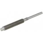
| Product name | Lead Screws -For Support Units-? |
| Part number | MTSWK14-240-S70-RC-FE13-FW6-FY1 |
| Features | A dedicated lead screw configured for bearings, stopper clamp, and a position indicator |
* Orange colored cells in the table below indicate the part numbers used in this example.
Selection criteria
Effective as a motion transmission device to move the tale, etc.
Back to page top
Available sizes
■Lead screw support unit
| Lead screw | Compatible lead screw nut |
| Type | Material | Surface treatment | Type | Material |
Right hand thread
・
Lent hand thread | 1045 Carbon Steel | ? | Right hand thread
・
Lent hand thread | Brass |
| Black oxide |
| Low temperature black chrome plating |
| 303 Stainless Steel | ? |
■Sizes and Dimensions
| Screw shaft nominal DIA. | Pitch | Overall length | Applicable bearing | Handle mounting shaft |
| 1mm increment | I.D. | Width | DIA. | Length |
| 12 | 2 | 80~1000 | φ8 | ≦7 | φ6 | 2~80 |
| 14 | 3 | φ10 | ≦8 | φ8 |
| 16 | 100?1200 | φ12 | ≦8 | φ10 | 2~95 |
| 18 | 4 | 150?1200 |
| 20 | φ15 | ≦9 | φ12 | 2~100 |
| 22 | 5 |
| 25 |
* Manufacturable ranges vary slightly depending on material, screw shaft nominal DIA. Please see the product pages for details.
Back to page top
Accuracy Info
■Lead screw: Screw shaft runout tolerance (Max.)
(mm)
Screw shaft
nominal | Screw shaft length |
| -125 | 126
-200 | 201
-315 | 316
-400 | 401
-500 | 501
-630 | 631
-800 | 801
-1000 | 1001-1200 |
| 12 | 0.09 | 0.12 | 0.16 | 0.21 | 0.27 | 0.35 | 0.46 | 0.58 | - |
| 14 | 0.09 | 0.11 | 0.13 | 0.16 | 0.2 | 0.25 | 0.32 | 0.42 | - |
| 16 | 0.09 | 0.11 | 0.13 | 0.16 | 0.2 | 0.25 | 0.32 | 0.42 | 0.55 |
| 18-20 | - | 0.11 | 0.13 | 0.16 | 0.2 | 0.25 | 0.32 | 0.42 | 0.55 |
| 22-25 | - | 0.09 | 0.11 | 0.13 | 0.16 | 0.19 | 0.23 | 0.3 | 0.38 |
■Lead screw accuracy standards
| Item | Value |
| Allowable dimension limit and tolerances | JISB0217 0218 |
| Screw accuracy | 7e Class |
| Nut accuracy | 7H Class |
| Single pitch error | ±0.02 |
| Cumulative pitch error | ±0.15/300mm |
| Length tolerance | JISB0405(Medium class) |
| Screw shaft end DIA. tolerance | h7 |
■Shaft end DIA. tolerance
| Bearing shaft DIA. | Shaft end DIA. | Tolerance |
| φ8 | φ5 | +0.075/0 |
| φ10 | φ9.6 | 0/-0.09 |
| φ12 | φ11.5 | 0/-0.11 |
| φ15 | φ14.3 |
Back to page top
Technical calculations
■Lead screw・Lead screw nut selection steps
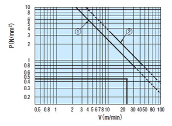
In order to verify contact surface pressure and sliding speed not to cause abnormal wear on the lead screw nut, obtain surface contact pressure P and sliding speed V.
Plot the calculated P and V values against the PV value graph and confirm the intersection.
If the intersection falls inside of line ① and ②, it is determined that abnormal wear would not occur.
Determining of usage conditions
↓
Lead screw・lead screw nut temporary selection
↓
① Contact surface pressure P, ②Sliding speed V calculations
Verify that the value is within ① and ②of the PV value graph
↓
Calculate screw efficiency η and load torque T.
(Axial load, rotational speed)
(Lead screw・lead screw nut material)
↑
(If not good)
- ① Steel (lubricated) - Brass
- ② Steel (unlubricated) - Resin
① Contact surface pressure P (N/mm²)
- Fs: Shaft axial load(N)
- F0: Allowable dynamic thrust (N) → From lead screw nut specifications
Thrust when contact surface pressure of the lead screw and nut becomes 9.8 (N/mm²). - α:9.8(Brass) 0.98(Resin)
② Sliding speed V (m/min)
- d2: Screw shaft effective DIA. → From lead screw specifications table
- d: Screw shaft lead angle (deg.) → From lead screw specifications table
- n: Screw shaft rotation per minute (nim-1)
③ Screw efficiency η
- μ: dynamic friction coefficient
- d: Screw shaft lead angle (deg.)
| Screw shaft | Lead screw nut | Dynamic friction coefficient μ |
| Steel (Lubricated) | Brass | 0.21 |
| Steel (Unlubricated) | Polyacetal/
sliding PPS resin | 0.13 |
④ Load torque (N・cm)
- Fs: Shaft axial load
- η: Screw efficiency
- R: Lead (cm)
Back to page top
Digital position indicator
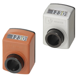
| Product name | Digital Positioning Indicators - Standard Splindle? |
| Part number | DSNR3-CSE8 |
| Features | Compact indicators can be mounted without occupying much space. Can be selected from 4 digit or 5 digit types. |
* Orange colored cells in the table below indicate the part numbers used in this example.
Selection criteria
Effective as a counter mountable without taking up a large space.
Back to page top
Available sizes
■Compact digital position indicator (Standard, Compact type)
| Cover | Displayed
digits | Rotation
direction | Back plate | Sleeve | Accessory |
| Material | Color | Material | Material | Surface treatment | Set screw | Cushion sheet |
| Nylon | Orange | 4 digits・5 digits | Right・Left | Polyphenylene ether | 1215 Carbon Steel | Black
oxide | 4137 Alloy Steel | Polyethylene foam
(Black) |
| Silver | 4 digits | (Black) |
■Specifications and Dimensions
| Spindle pitch | Count increment per revolution | Max. rotational speed | Applicable shaft DIA. | Reference dimension |
| 4 digits | 5 digits | (rpm) | Depth | Overall width | Overall height |
| 2 | 0002.0 | 00002.0 | 150 | φ6
φ8
φ10
φ12
φ14 | (33) | 33 | 47 |
| 3 | 0003.0 | 00003.0 | 100 |
| 4 | 0004.0 | 00004.0 | 75 |
| 5 | 0005.0 | 00005.0 | 60 |
| 6 | 0006.0 | 00006.0 | 50 |
Back to page top
IDEA NOTE Linear guide slant application
In order to minimize the equipment height and make manually operated handle rotation light, the linear guide is mounted diagonally and a wedge function is achieved.
IDEA NOTE Diagonally mounted linear guides are in rail moving configuration to secure the block spacing.
The rail of the linear guide is made to move to enable wide block spacing placed horizontally.
IDEA NOTE Horizontal leveling
There are 3 leveling bolts to level the engraving surface.


