(!) Since support from Microsoft will end on January 14 2020, Windows 7 user might not be able to use MISUMI website effectively. Please consider to update your system as ‘MISUMI Website system requirement’.


- inCAD Library Home
- > No.000034 Vertical Transfer Unit
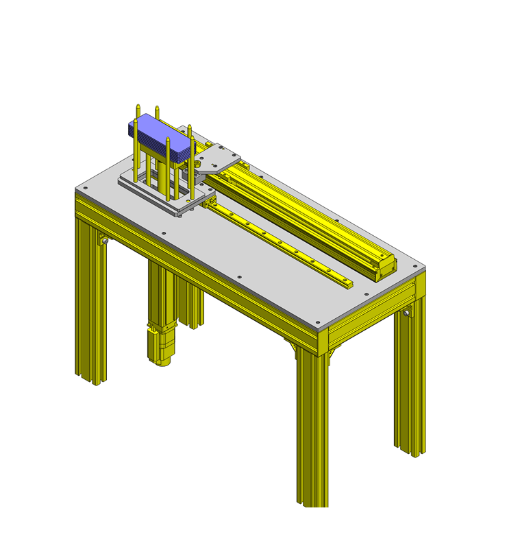
No.000034 Vertical Transfer Unit
62
Vertical transfer of workpiece using single axis actuator
Relevant category


Single axis robot Slider type

| Product name | Single Axis Robot RSH3 |
|---|---|
| Part number | RSH310-C21A-N-F1-3-500 |
Selection criteria
Linear motion unit that satisfies load capacity, stroke, and motion speed requirements.
Risk info.
Disconnection
Available sizes
Single axis robot (RSH3, Slider type)
General specifications
| Ball screw | Motor | Position detector | Operating atmosphere temp. ・ humidity | Controller power input |
|---|---|---|---|---|
| φ15 (C7 Rolled) | AC Servo motor 100W | Resolver | 0?40℃・35?85%RH (No condensation) | AC100-115V AC200-230V |
Basic specifications
| Lead (mm) | Stroke (mm) |
|---|---|
| 5 | 150-1050 (50Increment) |
| 10 | |
| 20 |
Dimensions ・ Mass
| Dimensions ・ Mass | Stroke | |||||||||
|---|---|---|---|---|---|---|---|---|---|---|
| 150 | 200 | 250 | 300 | 350 | 400 | 450 | 500 | 550 | 600 | |
| Overall length | 518 | 568 | 618 | 668 | 718 | 768 | 818 | 868 | 918 | 968 |
| Mass(kg) | 4.7 | 5 | 5.3 | 5.6 | 5.9 | 6.2 | 6.6 | 6.9 | 7.2 | 7.5 |
| Dimensions ・ Mass | Stroke | ||||||||
|---|---|---|---|---|---|---|---|---|---|
| 650 | 700 | 750 | 800 | 850 | 900 | 950 | 1000 | 1050 | |
| Overall length | 1018 | 1068 | 1118 | 1168 | 1218 | 1268 | 1318 | 1368 | 1418 |
| Mass(kg) | 7.8 | 8.1 | 8.4 | 8.7 | 9 | 9.3 | 9.7 | 10 | 10.3 |
Selection steps
Single axis robot selection steps
Load capacity
↓
Stroke
↓
Cycle time or Max. Speed
↓
Detail confirmation
Accuracy Info
Accuracy of Single Axis Robot
Repeatability: ±0.01mm
Performance info.
Basic specifications
| Lead (mm) | Max. load capacity | Rated force (N) | Max. speed (mm/sec) | Rated Life |
|---|---|---|---|---|
| Horizontal (kg) | ||||
| 5 | 80 | 339 | 300-105 | 10,000km or more |
| 10 | 60 | 169 | 600-210 | |
| 20 | 30 | 84 | 1200-420 |
Max. speed(mm/sec)
| Lead (mm) | Stroke | |||||||||
|---|---|---|---|---|---|---|---|---|---|---|
| 150-600 | 650 | 700 | 750 | 800 | 850 | 900 | 950 | 1000 | 1050 | |
| 5 | 300 | 255 | 225 | 195 | 180 | 165 | 150 | 135 | 120 | 105 |
| 10 | 600 | 510 | 450 | 390 | 360 | 330 | 300 | 270 | 240 | 210 |
| 20 | 1200 | 1020 | 900 | 780 | 720 | 660 | 600 | 540 | 480 | 420 |
Technical information
Convenient sizing software is available to use.

Linear guide
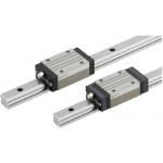
| Product name | Linear Guides - Heavy Load |
|---|---|
| Part number | SX2R28-760 |
| Features | Compliant with the industry standard specifications. |
Selection criteria
Suitable for linear guidance and as a load support.
Available sizes
Linear guide (For heavy loads ・ Normal clearance, Standard grade ・ 2 blocks ・ Standard blocks)
| Material | Hardness | Overall height | Rail length |
|---|---|---|---|
| Carbon steel (SCM etc. alloy steel) | 58HRC~ | 24 | 160-1480 |
| 28 | 220-1960 | ||
| 33 | 220-1960 |
Selection steps
Linear guide selection steps
- Determine application conditions
- (Mass of moving body, Feed rate, Motion pattern, Life)
↓
- Interim selection of linear guide specifications
- (Temporarily select block type, height,
rail length based on the application condition)
↓
- Confirm basic safety
-
- ● Load capacity
- ● Life
- ● Preload
Accuracy Info
Preload and accuracy standards

(μm)
| Tolerance of H | ±100 | |
|---|---|---|
| Pair variation of H | 20 | |
| Tolerance of W2 | ±100 | |
| Pair variation of W2 | H24・28 | 20 |
| H33 | 30 | |
(μm)
| Rail length | |||||||||
|---|---|---|---|---|---|---|---|---|---|
| -250 | 251-400 | 401-500 | 501-630 | 631-800 | 801-1000 | 1001-1250 | 1251-1600 | 1601-2000 | |
| Running parallelism | 7 | 12 | 14 | 18 | 21 | 23 | 25 | 27 | 28.5 |
Performance info.
Linear guide load rating (For heavy loads ・ Normal clearance ・ Standard grade)
| Overall height | Basic load rating | Allowable static moment | ||
|---|---|---|---|---|
| C (Dynamic) kN | C0 (Static) kN | MA・MB N・m | Mc N・m | |
| 24 | 8.6 | 14.2 | 69 | 98 |
| 28 | 12.5 | 21.3 | 155 | 232 |
| 33 | 20.2 | 34.5 | 275 | 393 |

Technical calculations
Linear guide life calculations
- ●Life
- When linear guides operate in linear motion while supporting loads, repeated stresses apply on the rolling elements (balls) and raceways (rails), eventually causing scale-like flaking due to material fatigue. The total run distance until this flaking appears is defined as linear guide's "Life".
- ●Rated life
- Rated life is a total distance 90% of linear guides reach without flaking when a group of the same guides are run under the same condition. The rated life can be calculated with basic dynamic load rating and the load applied on the guides as follows.
-

- When using linear guides, load calculations are initially needed. It is not easy to calculate the loads during linear motion due to vibrations and shocks, as well as load distribution on the guides. Furthermore, operating environment temperature has large effect on life. When these conditions are taken in consideration, the calculations would be as follows.
-

- L: Rated life (km)
- fH: Hardness factor (see Fig-1)
- fT: Temperature factor (see Fig-2)
- fC: Contact factor (see Table-1)
- fW: Load factor (see Table-2)
- C: Basic dynamic load rating (N)
- P: Applicable load (N)
- Hardness factor (fH)
-

In using linear guides, the shaft that balls contact must have sufficient hardness, If adequate hardness cannot be obtained, load rating decreases and life will be reduced as a result.
Please compensate the life rating with hardness factor.
- Temperature factor (fT)
-

When the temperature of linear guides exceed 100℃, hardness of blocks and rails will be reduced, causing reduction of life. Please compensate the life rating with temperature factor.
* Please use linear guides within temperature shown on product pages.
- Contact factor (fC)
-
Table-1. Contact factor
Number of blocks installed on one rail and contact factor fC
1 1.00 2 0.81 3 0.72 4 0.66 5 0.61 In general, it is common to use 2 or more blocks on 1 rail. In such case, load applicable on each block would not be uniform due to machining variations. As the result, allowable load rating on each block would vary depending on the number of blocks used per rail. Please compensate the life rating with contact factor shown on Table-1.
- Load factor (fW)
-
Table-2. Load factor
Application condition fw No external shocks or vibrations and
speed is low 15m/min or less1.0-1.5 No significant shocks or vibration and
med. speed 60m/min or less1.5-20 External shocks and vibrations exist
and the speed is high 60m/min or over2.0-3.5 When calculating loads applicable on linear guides, other than the weight of the object, inertial force due to motion speeds, moment loads, and variations of each over time must also be obtained accurately. However, accurate calculation would be difficult due to repeated starts and stops and various shocks and vibrations. Therefore, the Load Factors shown in Table-2 are used to simplify the life calculations.
- Applicable load calculation method
- When moment loads apply a block, use the following formula to convert the moment load to applicable load.
-

- P: Applicable load (N)
- F: Downward load (N)
- C0: Static load rating (N)
- MA: Allowable static moment - Pitching direction (N・m)
- MC: Allowable static moment - Rolling direction (N・m)
- Lp: Load point distance (m) in pitching direction
- Lr: Load point distance (m) in rolling direction

Cam follower

| Product name | Cam Followers - Hex Hole, No Seal, Crown Type |
|---|---|
| Part number | CFUA12-30 |
Selection criteria
Suitable for supporting linear transfer.
Available sizes
Cam follower (Crowned with a hex socket)
| Purpose | Main body | Nut | |||
|---|---|---|---|---|---|
| Material | Seal | Material | Surface treatment | ||
| No | Yes | ||||
| General | 52100 Bearing Steel | ○ | ○ | 1045 Carbon Steel | Black oxide |
| 440C Stainless Steel | ○ | ○ | 304 Stainless Steel | - | |
| Low particle generation | - | ○ | |||
| Heavy load | 52100 Bearing Steel | - | ○ | 1045 Carbon Steel | Black oxide |
| Stud DIA. | Thread | Outer race diameter | Outer race width | Overall length |
|---|---|---|---|---|
| φ8 | M8x1.25 | φ19 | 11 | 32 |
| φ10 | M10x1.25 | φ22 | 12 | 36 |
| φ26 | ||||
| φ12 | M12x1.5 | φ30 | 14 | 40 |
| φ32 | ||||
| φ16 | M16x1.5 | φ35 | 18 | 52 |
Accuracy Info
Cam follower accuracies
Stud diameter tolerance: h7
Outer ring DIA. Tolerance: 0/-0.05
Outer race DIA. Tolerance: 0/0.12
Performance info.
Cam follower reference data
| Stud DIA. -Outer race diameter | General | |||||
|---|---|---|---|---|---|---|
| Basic dynamic load rating C(kN) | Basic static load rating Cor(kN) | Max allowable load(kN) | Track load capacity (Crowned)(kN) | Rotational speed limit (rpm) | ||
| With Seal | Without Seal | |||||
| 8-19 | 4.17 | 4.65 | 4.73 | 1.37 | 14000 | 20000 |
| 10-22 | 5.33 | 6.78 | 5.81 | 1.67 | 11900 | 17000 |
| 10-26 | 2.06 | |||||
| 12-30 | 7.87 | 9.79 | 9.37 | 2.45 | 9800 | 14000 |
| 12-32 | 2.74 | |||||
| 16-35 | 12.00 | 18.30 | 17.30 | 3.14 | 7000 | 10000 |
| Stud DIA. -Outer race diameter | Heavy load | ||||
|---|---|---|---|---|---|
| Basic dynamic load rating C(kN) | Basic static load rating Cor(kN) | Max allowable Load(kN) | Track load capacity (Crowned)(kN) | Rotational speed limit (rpm) | |
| With Seal | |||||
| 8-19 | 8.13 | 11.20 | 4.73 | 1.37 | 3480 |
| 10-22 | 9.42 | 14.30 | 5.81 | 1.67 | 2880 |
| 10-26 | 2.06 | ||||
| 12-30 | 13.40 | 19.80 | 9.37 | 2.45 | 2320 |
| 12-32 | 2.74 | ||||
| 16-35 | 20.60 | 37.60 | 17.30 | 3.14 | 1800 |


IDEA NOTE Floating mechanism
The connection between robot and slide table is floating structure utilizing cam follower.


-

-
 Terms of use of CAD data and simplified drawing data
- These terms and conditions (hereinafter referred to as “the Terms") set forth the conditions for downloading CAD data and simplified drawing data posted on https://th.misumi-ec.com/ (hereinafter referred to as the "Website") operated by MISUMI (THAILAND) CO., LTD. (hereinafter referred to as "MISUMI"). By downloading CAD data and simplified drawing data posted on the Website (hereafter referred to as “Data”), customers are deemed to have agreed to these Terms.
- 1. Purpose of Use
-
MISUMI offers the following:
1)CAD data found on the Website (3D CAD data, 3D Intermediate data and 2D CAD data) for the purpose of informing customers of the characteristics of the products offered by MISUMI or a manufacturer affiliated with MISUMI for use in their designs.
2)Simplified drawing data (in PDF format) for the purpose of checking the specifications of products. - 2. Characteristics of Data
- There may be a discrepancy in certain characteristics of products (for example: tolerance, surface roughness, chamfer, etc.) between the Data and the actual product. Furthermore, for the purpose of reducing the file size of the Data, some information such as oil groove shapes, threads, or spring shapes, may be removed from the Data.
- 3. Disclaimer
- MISUMI carefully creates the Data but makes no warranty as to the accuracy of the Data. MISUMI may at any time, and with no prior notice to customers, revise or delete Data. MISUMI assumes no responsibility for any damage or loss resulting from any revision or deletion of the Data, or any errors in said data. Customers are solely responsible for all aspects of their own designs, including those made using MISUMI’s CAD data. MISUMI may provide customers with design example data on the Website, but the quality, accuracy, functionality, safety, reliability, etc., of such data are not guaranteed. MISUMI may, at any time, and in its sole discretion, request that the customer cease its use of or destroy the Data in its possession. MISUMI may request the customer provide MISUMI documentation of such destruction.
- 4.Prohibited Acts
-
Customers or users of the Data, are prohibited from the following acts regarding the Data, in whole or in part:
(1)Requesting quotations or placing orders for products with third parties other than those authorized by MISUMI or its affiliates;
(2)Receiving quotations or orders for products from third parties by providing the Data to a third party or using the Data in their own business;
(3)Displaying links to the Website related to the Data on their own websites, etc., without MISUMI's consent;
(4)Using or reproducing the Data beyond the scope of the above-stated Purpose of Use;
(5)Modifying, altering, tampering with, translating, or adapting the Data;
(6)Selling, transferring, lending, sublicensing, or providing the Data to third parties in any way without MISUMI’s consent;
(7)Altering the content, reverse engineering, decompiling, disassembling, or analyzing the Data;
(8)Publicly disclosing or exhibiting the Data without MISUMI's consent;
(9)Using the Data for the purpose of providing products and services identical or similar to those of MISUMI;
(10)Performing acts that interfere with the proper functioning of this Website, such as acquiring Data in bulk. - 5. Copyright
-
All title and copyright in and to any information contained in the Data are owned by MISUMI or the relevant manufacturer affiliated with MISUMI and are protected by applicable copyright laws and international treaties. By downloading Data, the customer acquires no ownership rights of any kind in the intellectual property contained within. Without prior approval from MISUMI, no part of the Data may be utilized (reproduced, modified, reverse-engineered, uploaded, presented, sent, distributed, licensed, sold, or published) for any purpose other than that mentioned above.
In the event Data is found to have been to be used for any purpose other than that mentioned above or against any applicable laws, MISUMI may pursue any legal remedy available to it, which may result in forbidding the offending user from using the Data or accessing the Website. - 6. Third-Party Data
- MISUMI offers some Data provided by third parties. Such Data may be subject to separate terms and conditions, in addition to these terms. MISUMI makes no guarantee or warranty regarding Data from third parties.
- 7. Export Control
- Customers shall comply with all applicable laws and regulations regarding the export of the Data.
- 8. Amendments to the Terms
- MISUMI may, at any time, and in its sole discretion, modify these terms and conditions; any such modification will be effective immediately.
- 9. Severability
- If any term or provision of these Terms is invalid, illegal, or unenforceable in any jurisdiction, such invalidity, illegality, or unenforceability shall not affect any other term or provision of these Terms or invalidate or render unenforceable such term or provision in any other jurisdiction.
- 10.Miscellaneous
- These Terms and any disputes arising in connection therewith shall be exclusively governed by and construed in accordance with the laws of Thailand, without regard to its conflicts of law principles. The authorized courts in Thailand shall have exclusive jurisdiction to adjudicate any dispute arising in connection with these Terms.
- Revised: 16th November, 2025
CAD Download (Unit Assembly)
CAD Download: File Format
CAD Data Limitations
-
Assembly data shows the assembly drawings in the concept design phase. The sole purpose of the data is to explain the structure and functionality of the assembly and is not considered nor to be used as a final design.
You will need to edit the Data so that it meets your specific design conditions. -
Unit assembly Data consists of some sub-assemblies.
It is configured so that each sub-assembly unit can be used as it is or edited. - The Data for fabricated parts is based on easy-to-edit dimensions and shapes in sketches and histories.
- The Data including the third-part components are made by the Company.
* The part in the frame is a sub-assembly unit.
-

- * Unit assembly Data consists of some sub-assemblies.
It is configured so that each sub-assembly unit can be used as it is or edited.
Application Overview
Purpose
- A workpiece is vertically elevated using a single axis actuator.
Target workpiece
- Plastic plate
W188 x D68 x t5
Design Specifications
Operating Conditions or Design Requirements
- External dimensions: W400 x L900 x (H593)
- Stroke(Left/Right):500mm
- Stroke(Up/Down):200mm
Required Performance
- Positioning accuracy
Left/Right: ±0.2/500 mm
Up/Down: ±0.2/200 mm
Selection Criteria for Main Components
- A single axis robot is used for multi-point positioning capability and a long stroke.
- A single axis robot is used since acceleration/deceleration and good positioning accuracy are needed.
Design Evaluation
Verification of main components
- Select a robot that satisfies load capacity, stroke, and motion speed requirements.
- Single axis robot selection calculations
- X axis robot
(1) Load capacity → Select from [Max load capacity] of Spec. List: 10kg (98N)
(2) Stroke → Select from [Stroke] of Spec. list: 500mm
(3) Cycle time → Select from [Cycle time graph] or [Max speed]: 1.2sec
Temporarily select RSH310-C21A-N-F1-3-500
(4) Detail confirmation
Overhang: 111mm allowable at 20kg, actual overhang 68mm.
Bending moment: 98N×0.068m=6.7N·m
Selected model's allowable moment is 163N·m, and is sufficient for this application. - Z axis robot
(1) Load capacity → Select from [Max load capacity] of Spec. List: 10kg (98N)
(2) Stroke → Select from [Stroke] of Spec. list: 200mm
(3) Max speed → Select from [Max speed] of spec. list: 80mm/sec
Temporarily select RSDG306B-C1-N-3-200
(4) Detail confirmation
Max push force: 10 x 9.8 = 98N, the max allowable push force is 550N, therefore selected robot satisfies load requirements.
- X axis robot
Other Design Consideration
- Ensure the aluminum extrusion frame has sufficient rigidity to provide the necessary weight capacity.
Explore Similar Application Examples

-

-

-

-

-

-

-

-

-

-

-

-

-

-

-

-

-

-

Relevant category
-

-

-

-

-

-

-

-

-

-

-

-

-

-

-

-

-

-

-

-

-

-

-

-

-

-

-

-

-

-

-

-

-

-

-

Relevant category
-

-

-

-

-

-

-

-

-

-

-

-

-

-

-

-

-

-

-

-

-

-

-

-

-

-

-

-

-

-

-

-

-

-

-

-

-

-

-

-

-

-

-

-

-

-

-

-

-

-

-

-


Payment Methods
- Bank
-
- Prompt Pay
-


- Cash
-

- Cash on Delivery
Social Media
MISUMI Contact
Copyright © MISUMI Corporation All Rights Reserved.