(!) Since support from Microsoft will end on January 14 2020, Windows 7 user might not be able to use MISUMI website effectively. Please consider to update your system as ‘MISUMI Website system requirement’.


- inCAD Library Home
- > No.000075 Rotate and Transfer Mechanism
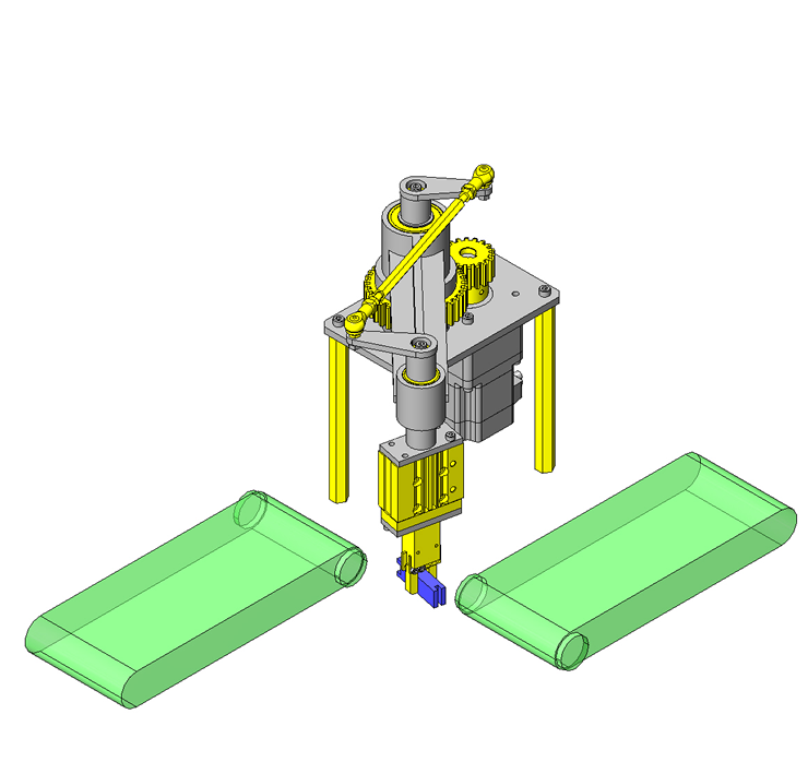
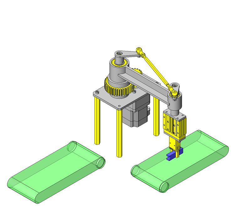
No.000075 Rotate and Transfer Mechanism
102
Motor and gear system rotates the arm and gripper simultaneously.
Relevant category


Spur Gears

| Product name | Induction Hardened Spur Gears - Pressure Angle 20Deg. |
|---|---|
| Part number | GEAHBH2.0-36-20-A-35 |
| Features | Gears with hardened teeth which provides excellent strength, abrasion resistance and high precision |
Selection criteria
A gear is placed to reduce the speed of the motor output rotation by half
Available sizes
■Induction Hardened Spur Gears (Ground)
| Material | Surface Treatment | Hardness | Accessory |
|---|---|---|---|
| 1045 Carbon Steel | Black Oxide | Tooth Induction Hardened 51 - 55 HRC (depth 1 mm or more) | Set screw (4137 Alloy Steel Black Oxide) |
■Sizes and Dimensions
| Module | Number of Teeth | Shaft bore DIA. (1 mm Increments) | |
|---|---|---|---|
| Round Hole Round Hole + Tap | Keyway Keyway + Tap | ||
| 2.0 | 15 | 12-17 | 12-14 |
| 16 | 12-18 | 12-15 | |
| 18 | 12-21 | 12-18 | |
| 20 | 15-22 | 15-19 | |
| 22 | |||
| 24 | 15-26 | 15-23 | |
| 25 | 15-28 | 15-24 | |
| 28 | 15-31 | 15-28 | |
| 30 | 18-35 | 18-31 | |
| 32 | |||
| 36 | |||
| 40 | 20-42 | 20-38 | |
| 45 | |||
| 48 | |||
| 50 | 25-42 | 25-38 | |
| 60 | 25-45 | 25-42 | |
| 2.5 | 16 | 15-22 | 15-19 |
| 20 | 18-28 | 18-24 | |
| 24 | 18-33 | 18-30 | |
| 25 | 20-35 | 20-31 | |
| 28 | 20-42 | 20-38 | |
| 30 | 20-45 | 20-42 | |
| 36 | 20-49 | 20-45 | |
| 40 | 25-49 | 25-45 | |
| 45 | 25-52 | 25-49 | |
| 48 | |||
| 50 | 25-56 | 25-50 | |
Accuracy Info
■Accuracy of Induction Hardened Spur Gears (Ground)
Gear accuracy: Previous JIS B 1702 Class 2 (New JIS B 1702-1 Class 6 equivalent)
Shaft bore DIA. tolerance: H7

Rod End Bearings

| Product name | Rod End Bearings - 90 Deg. Link Ball Type |
|---|---|
| Part number | RBLD5 |
Selection criteria
Connecting link mechanism.
Available sizes
■Rod End Bearings (Link Ball L Type / Right hand thread)
| Material | |
|---|---|
| Holder | High Strength Zinc Alloy * M4, 5: High Strength Aluminum Alloy |
| Shank with Ball | 1035 Carbon Steel |
| Boots | NBR Type Special Synthetic Rubber |
■Sizes and Dimensions
| Thread Dia. | Ball Center - Holder Edge | Ball Center - Shank Edge |
|---|---|---|
| 4 | 18 | 15 |
| 5 | 27 | 21 |
| 6 | 30 | 26 |
| 8 | 36 | 31 |
| 10 | 43 | 43 |
| 10(Fine Thread) | 37 | |
| 12 | 50 | 49 |
| 12(Fine Thread) | 42 | |
| 14 | 57 | 62 |
| 14(Fine Thread) | 56 | |
| 16 | 64 | 66 |
| 16(Fine Thread) | 60 |
Accuracy Info.
■Allowable Incline Angle of Rod End Bearings
| Thread Dia. | Allowable Incline Angle |
|---|---|
| 4 | 40° |
| 5 | |
| 6 | |
| 8 | |
| 10 | |
| 10(Fine Thread) | |
| 12 | |
| 12(Fine Thread) | |
| 14 | |
| 14(Fine Thread) | |
| 16 | 30° |
| 16(Fine Thread) |
Performance info.
■Yield Strength and Static Load Capacity of Rod End Bearings
| Thread Dia. | Yield Strength (N) | Static Load Capacity (N) |
|---|---|---|
| 4 | 1370 | 4510 |
| 5 | 2250 | 6470 |
| 6 | 3920 | 9900 |
| 8 | 6570 | 12500 |
| 10 | 11300 | 18300 |
| 10(Fine Thread) | ||
| 12 | 16400 | 26700 |
| 12(Fine Thread) | ||
| 14 | 19800 | 36400 |
| 14(Fine Thread) | ||
| 16 | 26900 | |
| 16(Fine Thread) |

Rod End Coupling Rods

| Product name | Rod End Coupling Rods - Both Ends Threaded |
|---|---|
| Part number | LBRFN5-180 |
| Features | Rod End Coupling Rods with the right-hand/left-hand thread selectable in size and length. |
Selection criteria
To connect rod end bearings.
Available sizes
■Rod End Coupling Rods (Both Ends Threaded, Length Configurable)
| Material | Surface Treatment | Accessory (one hex nut for right / left-hand thread) | |
|---|---|---|---|
| Material | Surface Treatment | ||
| 1045 Carbon Steel | Black Oxide | 1045 Carbon Steel | Trivalent Chromate |
| Electroless Nickel Plating | |||
| 304 Stainless Steel | - | 304 Stainless Steel | - |
■Sizes and Dimensions
| Thread Dia. (Coarse) | Overall Length | Thread Length (Under Head) | Opposite Side |
|---|---|---|---|
| 3 | 25-39 | 8 | 6 |
| 40-300 | 15 | ||
| 4 | 35-49 | 12 | 7 |
| 50-400 | 20 | ||
| 5 | 40-59 | 13 | 8 |
| 60-600 | 25 | ||
| 6 | 50-69 | 17 | 10 |
| 70-600 | 30 | ||
| 8 | 60-89 | 23 | 13 |
| 90-1000 | 40 | ||
| 10 | 70-109 | 28 | 17 |
| 110-1000 | 50 | ||
| 12 | 80-129 | 33 | 19 |
| 130-1000 | 60 | ||
| 14 | 130-1000 | 60 | 21 |
| 16 | 170-1000 | 80 | 24 |
| 18 | 170-1000 | 80 | 27 |
| 20 | 170-1000 | 80 | 30 |
| 22 | 170-1000 | 80 | 32 |


-

-
 Terms of use of CAD data and simplified drawing data
- These terms and conditions (hereinafter referred to as “the Terms") set forth the conditions for downloading CAD data and simplified drawing data posted on https://th.misumi-ec.com/ (hereinafter referred to as the "Website") operated by MISUMI (THAILAND) CO., LTD. (hereinafter referred to as "MISUMI"). By downloading CAD data and simplified drawing data posted on the Website (hereafter referred to as “Data”), customers are deemed to have agreed to these Terms.
- 1. Purpose of Use
-
MISUMI offers the following:
1)CAD data found on the Website (3D CAD data, 3D Intermediate data and 2D CAD data) for the purpose of informing customers of the characteristics of the products offered by MISUMI or a manufacturer affiliated with MISUMI for use in their designs.
2)Simplified drawing data (in PDF format) for the purpose of checking the specifications of products. - 2. Characteristics of Data
- There may be a discrepancy in certain characteristics of products (for example: tolerance, surface roughness, chamfer, etc.) between the Data and the actual product. Furthermore, for the purpose of reducing the file size of the Data, some information such as oil groove shapes, threads, or spring shapes, may be removed from the Data.
- 3. Disclaimer
- MISUMI carefully creates the Data but makes no warranty as to the accuracy of the Data. MISUMI may at any time, and with no prior notice to customers, revise or delete Data. MISUMI assumes no responsibility for any damage or loss resulting from any revision or deletion of the Data, or any errors in said data. Customers are solely responsible for all aspects of their own designs, including those made using MISUMI’s CAD data. MISUMI may provide customers with design example data on the Website, but the quality, accuracy, functionality, safety, reliability, etc., of such data are not guaranteed. MISUMI may, at any time, and in its sole discretion, request that the customer cease its use of or destroy the Data in its possession. MISUMI may request the customer provide MISUMI documentation of such destruction.
- 4.Prohibited Acts
-
Customers or users of the Data, are prohibited from the following acts regarding the Data, in whole or in part:
(1)Requesting quotations or placing orders for products with third parties other than those authorized by MISUMI or its affiliates;
(2)Receiving quotations or orders for products from third parties by providing the Data to a third party or using the Data in their own business;
(3)Displaying links to the Website related to the Data on their own websites, etc., without MISUMI's consent;
(4)Using or reproducing the Data beyond the scope of the above-stated Purpose of Use;
(5)Modifying, altering, tampering with, translating, or adapting the Data;
(6)Selling, transferring, lending, sublicensing, or providing the Data to third parties in any way without MISUMI’s consent;
(7)Altering the content, reverse engineering, decompiling, disassembling, or analyzing the Data;
(8)Publicly disclosing or exhibiting the Data without MISUMI's consent;
(9)Using the Data for the purpose of providing products and services identical or similar to those of MISUMI;
(10)Performing acts that interfere with the proper functioning of this Website, such as acquiring Data in bulk. - 5. Copyright
-
All title and copyright in and to any information contained in the Data are owned by MISUMI or the relevant manufacturer affiliated with MISUMI and are protected by applicable copyright laws and international treaties. By downloading Data, the customer acquires no ownership rights of any kind in the intellectual property contained within. Without prior approval from MISUMI, no part of the Data may be utilized (reproduced, modified, reverse-engineered, uploaded, presented, sent, distributed, licensed, sold, or published) for any purpose other than that mentioned above.
In the event Data is found to have been to be used for any purpose other than that mentioned above or against any applicable laws, MISUMI may pursue any legal remedy available to it, which may result in forbidding the offending user from using the Data or accessing the Website. - 6. Third-Party Data
- MISUMI offers some Data provided by third parties. Such Data may be subject to separate terms and conditions, in addition to these terms. MISUMI makes no guarantee or warranty regarding Data from third parties.
- 7. Export Control
- Customers shall comply with all applicable laws and regulations regarding the export of the Data.
- 8. Amendments to the Terms
- MISUMI may, at any time, and in its sole discretion, modify these terms and conditions; any such modification will be effective immediately.
- 9. Severability
- If any term or provision of these Terms is invalid, illegal, or unenforceable in any jurisdiction, such invalidity, illegality, or unenforceability shall not affect any other term or provision of these Terms or invalidate or render unenforceable such term or provision in any other jurisdiction.
- 10.Miscellaneous
- These Terms and any disputes arising in connection therewith shall be exclusively governed by and construed in accordance with the laws of Thailand, without regard to its conflicts of law principles. The authorized courts in Thailand shall have exclusive jurisdiction to adjudicate any dispute arising in connection with these Terms.
- Revised: 16th November, 2025
CAD Download (Unit Assembly)
CAD Download: File Format
CAD Data Limitations
-
Assembly data shows the assembly drawings in the concept design phase. The sole purpose of the data is to explain the structure and functionality of the assembly and is not considered nor to be used as a final design.
You will need to edit the Data so that it meets your specific design conditions. -
Unit assembly Data consists of some sub-assemblies.
It is configured so that each sub-assembly unit can be used as it is or edited. - The Data for fabricated parts is based on easy-to-edit dimensions and shapes in sketches and histories.
- The Data including the third-part components are made by the Company.
* The part in the frame is a sub-assembly unit.
-

- * Unit assembly Data consists of some sub-assemblies.
It is configured so that each sub-assembly unit can be used as it is or edited.
Application Overview
Purpose
- Transfers work pieces on a conveyor to the next process by rotating the work piece 180°. The arm rotates the work piece the first 90° and the linkage rotates the gripper the second 90°.
- Gripper down→Retain workpiece→Gripper up→ 90° rotate & transfer・Workpiece rotate 90°→Gripper down →Workpiece released →Gripper up.
Target workpiece
- Shape: Connector
Size: W50×D10×H15mm
Weight: 0.1 kg
Design Specifications
Operating Conditions or Design Requirements
- Transfer angle: 90 degrees
- Workpiece rotation angle: 90 degrees
- Cylinder stroke: 20mm
- Clamp stroke: 10mm
- External dims: W100 x D317 x H269 (Before rotation)
Selection Criteria for Main Components
- Ratio of fixed linkage and moving linkage ratio to be 1:1.
- Suppress inertia by reducing weight of swinging components.
- Confirm that the gear is strong enough to withstand the inertial force.
- Select the air gripper based on friction coefficient and workpiece weight.
Design Evaluation
Verification of main components
- It is important to calculate the inertia that applies to the stepper motor. The calculations are below.
- Time that takes to move 90° t 1 : 0.5sec
- Acceleration time t 0 : 0.01sec
- Swinging and rotating arm inertia moment: J 1 =4.063×10 ⁻² ㎏・㎡
- Inertia moment of a gear on the motor shaft: J 2 =3.598×10 ⁻ ⁵ ㎏・㎡
- Inertia moment applicable to motor shaft: Since it is via gear, JL = J 1 ×(Number of Teeth of sm. gear / Number of Teeth of L. gear) ² +J 2 =1.019×10 ⁻² ㎏・㎡
- Operating pulses:A=θ/θs=1250pulses
Here, the operating angle:θ=90°, Min. step angle of stepping motor:θs=0.072° - Operational pulse rate: f2 2 =A/(t 0 -t 1 )=3125Hz
- Motion speed: NM=θs/360×f 2 ×60=37.5r/min
- Inertia moment of motor's rotor: J = 0 =2.8×10 ⁻ ⁵
- Motor gear ratio: i = 10
- Acceleration torque calculation: Ta = (J 0 ・i ² +JL)/9.55×NM/t 1 =0.51N・m
- Calculation of required torque:TM=Ta×Safety margin=1.02N・m Safety ratio given: 2) Select motor from torque characteristics chart.Motor is OK
- Verifying inertia ratio: JL/ (J 0 ×i ² )=3.64≦10 is OK
Other Design Consideration
- The main shaft (center of rotation) and linkage arm to the main shaft are fixed.
- The gripper at rotation end can elevate and rotate.
Explore Similar Application Examples

-

-

-

-

-

-

-

-

-

-

-

-

-

-

-

-

-

-

-

Relevant category
-

-

-

-

-

-

-

-

-

-

-

-

-

-

-

-

-

-

-

-

-

-

-

-

-

-

-

-

-

-

-

-

-

-

-

-

-

Relevant category
-

-

-

-

-

-

-

-

-

-

-

-

-

-

-

-

-

-

-

-

-

-

-

-

-

-

-

-

-

-

-

-

-

-

-

-

-

-

-

-

-

-

-

-

-

-

-

-

-

-

-

-

-

-

-

-

-

-

-

-

-

-

-

-

-

-

-


Payment Methods
- Bank
-
- Prompt Pay
-


- Cash
-

- Cash on Delivery
Social Media
MISUMI Contact
Copyright © MISUMI Corporation All Rights Reserved.