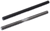
Lead Screw
| Product name | Lead Screws - Straight |
| Part number | MTSTR16-474 |
* Orange colored cells in the table below indicate the part numbers used in this example.
Selection criteria
Converts rotary to linear motion.
Available sizes
■Lead Screws - Straight
| Material | Surface Treatment | Compatible lead screw nut |
| Type | Material |
| 1045 Carbon Steel | - | Right-hand Thread | Brass |
| Black Oxide |
| 303 Stainless Steel | - |
■Sizes and Dimensions
| Screw shaft nominal | Pitch | Overall Length |
| 1mm Increment | 100 mm Increments |
| 8 | 1.5 | 50?500 | - |
| 10 | 2 | 80?1000 |
| 12 |
| 14 | 3 |
| 16 | 100?1200 | 1300~2000 |
| 18 | 4 | 150?1200 |
| 20 |
| 22 | 5 |
| 25 |
| 28 |
| 32 | 6 | 200?1200 |
| 36 |
| 40 |
| 50 | 8 | - |
* Manufacturable ranges vary slightly depending on material or screw shaft nominal Dia. Please see the product pages for details.
Back to page top
Accuracy Info
■Lead screw: Screw shaft runout tolerance (Max.)
(mm)
| Shaft Dia. | Screw shaft length |
| -125 | 126
-200 | 201
-315 | 316
-400 | 401
-500 | 501
-630 | 631
-800 | 801
-1000 | 1001-1250 | 1251-1600 | 1601-2000 |
| φ8 | 0.1 | 0.14 | 0.21 | 0.27 | 0.35 | - | - | - | - | - | - |
| φ10-12 | 0.09 | 0.12 | 0.16 | 0.21 | 0.27 | 0.35 | 0.46 | 0.58 | - | - | - |
| φ14 | 0.09 | 0.11 | 0.13 | 0.16 | 0.2 | 0.25 | 0.32 | 0.42 | - | - | - |
| φ16 | 0.09 | 0.11 | 0.13 | 0.16 | 0.2 | 0.25 | 0.32 | 0.42 | 0.55 | 0.73 | 1 |
| φ18-20 | - | 0.11 | 0.13 | 0.16 | 0.2 | 0.25 | 0.32 | 0.42 | 0.55 | 0.73 | 1 |
| φ22-32 | - | 0.09 | 0.11 | 0.13 | 0.16 | 0.19 | 0.23 | 0.3 | 0.38 | 0.5 | 0.69 |
| φ36-50 | - | 0.11 | 0.11 | 0.11 | 0.13 | 0.15 | 0.17 | 0.22 | 0.27 | 0.34 | 0.46 |
■Lead Screw Accuracy Standards
| Item | Content |
| Allowable Dimension and Tolerance | JISB0217 0218 |
| Screw Accuracy | 7e Class |
| Nut Accuracy | 7H Class |
| Single Pitch Error | ±0.02 |
| Accumulated Pitch Error | ±0.15/300mm |
| Length tolerance | JISB0405(Medium class) |
| Screw shaft end DIA. tolerance | h7 |
Back to page top
Technical calculations
■Lead screw・Lead screw nut selection steps
Calculate Contact Pressure P and Sliding Velocity V based on conditions of use to check that no abnormal wear will occur.
Plot the calculated P and V values against the PV value graph and confirm the intersection.
If the intersection falls inside of line (1) and (2), it is determined that abnormal wear would not occur.
Determine conditions of use.
↓
Lead screw・lead screw nut temporary selection
↓
Calculate (1) Contact Pressure P, (2) Sliding Velocity V,
Confirm if it is inside of (1) and (2) on PV value graph.
↓
Calculate screw efficiency η and load torque T.
(Axial load, rotational speed)
(Lead screw・lead screw nut material)
↑
(If not good)
- ① Steel (lubricated) - Brass
- ② Steel (unlubricated) - Resin
(1) Contact surface pressure P (N/mm2)
- Fs: Shaft axial load(N)
- F 0 :Allowable Dynamic Thrust (N) -> Nuts for Lead Screw Specifications
Thrust when contact surface pressure of the lead screw and nut becomes 9.8 (N/mm2). - α:9.8(Brass) 0.98(Resin)
(2) Sliding speed V (m/min)
- d2: Screw shaft effective Dia. -> From lead screw specifications table
- d: Screw Shaft Lead Angle (degree) -> Lead Screw Specifications
- n: Screw shaft rotation per minute (nim-1)
(3) Screw efficiency η
- μ: dynamic friction coefficient
- d: Screw shaft lead angle (deg.)
<Dynamic friction coefficient reference value >
| Thread Shaft | Nuts for Lead Screws | Dynamic friction coefficient μ |
| Steel (Lubricated) | Brass | 0.21 |
| Steel (Unlubricated) | Polyacetal / PPS Resin
with Sliding Property | 0.13 |
(4) Load torque (N・cm)
- Fs: Shaft axial load
- η: Screw efficiency
- R: Lead (cm)
Back to page top
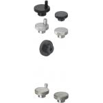
Aluminum Knurled Handwheel
| Product name | Knurled Handwheels - Aluminum |
| Part number | HOKW63 |
* Orange colored cells in the table below indicate the part numbers used in this example.
Selection criteria
Consider the operability, and select the one with appropriate O.D.
Available sizes
■Knurled Handwheels - Aluminum
| Handle | Handle | Handle Thread | Tapped |
| Material | Surface Treatment | Material | Material | Surface Treatment |
| 5056 Aluminum Alloy | Black anodize | Nylon 6(Black) | 12L13 Carbon Steel | Black Oxide | Tapped Hole |
| Without Tap |
| Clear Anodize | Nylon 6(White) | Tapped Hole |
| Without Tap |
| 304 Stainless Steel | - | 304 Stainless Steel | 304 Stainless Steel | - | Tapped Hole |
| Without Tap |
■Sizes and Dimensions
Knob
O.D. | Shaft Bore Dia. | | Handle Height | Handle | Set Screw Dia. |
(Black Handle, Black Grip,
Tapped) | Mounting height | Width | Diameter | Length |
| φ40 | φ8 | φ6・φ8 | 25 | 12 | φ13 | 18.8 | M5 |
| φ50 | φ10 | φ8・φ10 | 28 | 13 |
| φ63 | φ12 | φ10・φ12 | 32 | 14 | φ14 | 20.8 |
| φ80 | φ16 | φ12・φ16 | 40 | 15 | φ16 | 23.8 | M6 |
Back to page top
IDEA NOTE Simplified positioning (alignment) mechanism
Linear positioning is performed by utilizing a lead screw. Lead screw converts rotary motion from the handwheel to linear movement.


