(!) Since support from Microsoft will end on January 14 2020, Windows 7 user might not be able to use MISUMI website effectively. Please consider to update your system as ‘MISUMI Website system requirement’.
Over 300 design application ideas
collected from dozens of industries!
Log in to download free CAD models.
Download CAD for the entire application example!
Click the Good IDEA! Button when you like an application example!
*Can only be clicked once per application example.
Clamp mechanisms operated by pneumatic linear actuator.
Product name | Hinge Pins - Flanged, Threaded with Lock Nut |
---|---|
Part number | PCLBGHNU5-40 |
Suitable for oscillation fulcrum to hold down the workpiece.
■Hinge Pins - Flanged, Threaded with Lock Nut
Nut | Material | Hardness | Surface Treatment |
---|---|---|---|
Standard nut U-nut | 1045 Carbon Steel | ― | Black Oxide |
40-45HRC | |||
― | Electroless Nickel Plating | ||
40-45HRC | |||
Plating Hardness: 750 HV - | Hard Chrome Plating: Plating Thickness 3 µm or more | ||
304 Stainless Steel | ― | ― | |
440C Stainless Steel | 45-50HRC |
■Sizes and Dimensions
Pin Dia. (mm) | Length(mm) 0.1mm Increment | Screw Dia. (Coarse) |
---|---|---|
4 | 5.0- 50.0 | M3 |
5 | 5.0- 60.0 | M4 |
6 | 10.0-100.0 | M5 |
8 | M6 | |
10 | M8 | |
12 | 15.0-200.0 | M10 |
13 | 20.0-200.0 | M12 |
14 | ||
15 | ||
16 | 20.0-200.0 | |
17 | ||
18 | ||
20 | M16 | |
22 | ||
25 | ||
30 | 40.0-200.0 |
■Accuracy information of pivot pin
■Pin Dia. Tolerance:
Pin Dia. Tolerance(g6) | |
---|---|
4-6 | -0.004 -0.012 |
8・10 | -0.005 -0.014 |
12-18 | -0.006 -0.017 |
20-30 | -0.007 -0.020 |
Product name | Air Linear Guides - MPPU12 Series |
---|---|
Part number | MPPU12-45-SS |
Handy as Drive Source requiring no guidance.
■Pneumatically driven linear guides
I.D. of Cylinder | Horizontal (mm) | Vertical (mm) | Thickness (mm) | Stroke Length (mm) |
---|---|---|---|---|
φ10 | 27 | 70 | 20 | 15 |
85 | 30 | |||
100 | 45 | |||
φ12 | 32 | 76.5 | 22 | 20 |
86.6 | 30 | |||
101.6 | 45 | |||
116.6 | 60 |
■Accuracy Information of Pneumatically Driven Linear Guides
Unit: mm
Bore Dia. | φ10 | φ12 | ||
---|---|---|---|---|
Stroke | 15/30/45 | 20/30/45 | 60 | |
Parallelism | Plane C to Plane A | 0.02 | 0.02 | |
Plane D to Plane B | 0.02 | 0.02 | ||
Running parallelism | Plane C to Plane A | 0.004 | 0.004 | 0.006 |
Plane D to Plane B | 0.004 | 0.004 | 0.006 | |
直角度 | Plane E to Plane A | 0.15 | 0.15 | |
Plane E to Plane B | 0.15 | 0.15 | ||
J Dimension Tolerance | ±0.025 | ±0.025 | ||
F Dimension Tolerance | ±0.2 | ±0.2 | ||
G Dimension Tolerance | ±0.2 | ±0.2 | ||
H Dimension Tolerance | ±0.05 | ±0.05 |
■Performance info. of Pneumatically Driven Linear Guides
■Operating Pressure Range
Min. Operating Pressure (MPa): 0.15
Max. Operating Pressure (MPa): 0.70
Pressure Resistance (Mpa): 1.05
■Theoretical Thrust
Unit: N
Tube I.D. | Operation Direction | Rod Dia. (mm) | Operating Pressure (MPa) | |
---|---|---|---|---|
0.4 | 0.5 | |||
φ10 | Outstroke | φ4 | 31 | 39 |
Instroke | 26 | 33 | ||
φ12 | Outstroke | φ5 | 45 | 57 |
Instroke | 37 | 47 |
■Allowable Load Moment
Stroke (mm) | Allowable Load Moment N·m | ||
---|---|---|---|
Pitching | Yawing | Rolling | |
15/30/45 | 1.8 | 2.0 | 1.9 |
20/30/45/60 | 3.0 | 3.4 | 3.8 |
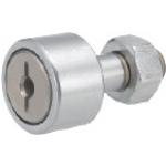
Product name | Cam Followers - Flat Type - No Seal |
---|---|
Part number | CFFRS5-13 |
Popular as lever holder.
■Cam Followers - Flat Type - No Seal
Grease | Seal | Material | Accessory | |
---|---|---|---|---|
Not Provided | Provided | |||
General | ○ | ○ | 52100 Bearing Steel | 1 Hex Nut (1045 Carbon Steel Iron Oxide Black Coating) |
○ | ○ | 440C Stainless Steel | Hex Nut 1 pc.(304 Stainless Steel ) | |
Low Dust Generation | ― | ○ |
■Sizes and Dimensions
Shaft DIA. (mm) | Outer Ring DIA. (mm) |
---|---|
5 | 13 |
6 | 16 |
8 | 19 |
10 | 22 |
26 | |
12 | 30 |
32 | |
16 | 35 |
18 | 40 |
20 | 52 |
■Accuracy Information of Cam Followers
■Shaft Dia. Tolerance
Shaft DIA. (mm) | h7 Tolerance |
---|---|
5 | 0 -0.012 |
6 | |
8 | 0 -0.015 |
10 | |
12 | 0 -0.018 |
16 | |
18 | |
20 | 0 -0.021 |
■Outer Race Dia. Tolerance
Outer Ring DIA.(mm) | Tolerance |
---|---|
13・16 | 0 -0.008 |
19-30 | 0 -0.009 |
32-40 | 0 -0.011 |
52 | 0 -0.013 |
■Speeds·Loads (Load info.) of cam followers
Shaft Dia. - Outer Ring Dia. (mm) | Basic Dynamic Load Rating (kN) | Basic Static Load Rating (kN) | Max. Allowable Load (kN) | Max. Rotational Speed (rpm) | |
---|---|---|---|---|---|
With Seal | No Seal | ||||
3-10 | 1.47 | 1.18 | 0.36 | 32900 | 47000 |
4-12 | 2.06 | 2.05 | 0.78 | 25900 | 37000 |
5-13 | 3.14 | 2.77 | 1.42 | 20300 | 29000 |
6-16 | 3.59 | 3.58 | 2.11 | 17500 | 25000 |
8-19 | 4.17 | 4.65 | 4.73 | 14000 | 20000 |
10-22 | 5.33 | 6.78 | 5.81 | 11900 | 17000 |
10-26 | |||||
12-30 | 7.87 | 9.79 | 9.37 | 9800 | 14000 |
12-32 | |||||
16-35 | 12.0 | 18.30 | 17.30 | 7000 | 10000 |
18-40 | 14.7 | 25.2 | 26.1 | 5950 | 8500 |
20-52 | 20.7 | 34.8 | 32.1 | 4900 | 7000 |
The workpiece being clamped by the spring is unclamped as the cylinder presses the pusher against the hinge block to incline the hinge to the center.
Thank you for downloading the data.
Click the Good IDEA! button when you find interesting design tips.
This data is utilized in order to list more useful application examples in the future.
* The part in the frame is a sub-assembly unit.
Chat service is available for any inquiry to MISUMI
9:00 - 18:00 (Mon-Sat)
For out of service hours, you can leave a message to us.
We will reply to your inquiries on the next business day.
(except Sundays and public holidays).
Chat service is for Corporate customers and limited for Thai language.
Request for Quotation and Place Order is not available on Chat.
Copyright © MISUMI Corporation All Rights Reserved.