(!) Since support from Microsoft will end on January 14 2020, Windows 7 user might not be able to use MISUMI website effectively. Please consider to update your system as ‘MISUMI Website system requirement’.


- inCAD Library Home
- > No.000210 Film Product Feeding Mechanism
No.000210 Film Product Feeding Mechanism
74
Film feeding mechanism with rollers.
Relevant category


Coupling
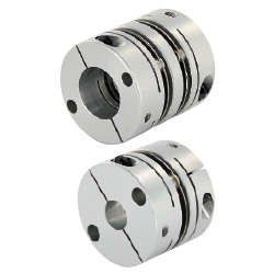
| Product name | Couplings - Disc, Clamping, For Servo Motor |
|---|---|
| Part number | CPDW25-8-8 |
Selection criteria
Select the double disc type with the larger allowable misalignment to improve the assembly performance.
Available sizes
■Couplings - Disc, Clamping, For Servo Motor
| Part | Material | Surface Treatment | Accessory |
|---|---|---|---|
| Main Body | Aluminum Alloy | Anodized | Hex Socket Head Cap Screw |
| Disc・Pin | Stainless Steel | - |
■Sizes and Dimensions
| O.D. | Shaft bore Dia. (Select drive / driven sides) | Overall Length | Clamp Screw Dia. | ||||||||||||||||||
|---|---|---|---|---|---|---|---|---|---|---|---|---|---|---|---|---|---|---|---|---|---|
| φ4 | φ5 | φ6 | φ6.35 | φ7 | φ8 | φ10 | φ11 | φ12 | φ14 | φ15 | φ16 | φ17 | φ18 | φ19 | φ20 | φ22 | φ24 | φ25 | |||
| φ19 | ○ | ○ | ○ | ○ | ○ | 18.5 | M2 | ||||||||||||||
| φ25 | ○ | ○ | ○ | ○ | ○ | ○ | 23 | M2.5 | |||||||||||||
| φ32 | ○ | ○ | ○ | ○ | ○ | ○ | 31 | M3 | |||||||||||||
| φ40 | ○ | ○ | ○ | ○ | ○ | ○ | ○ | ○ | ○ | ○ | ○ | 41 | M4 | ||||||||
| φ50 | ○ | ○ | ○ | ○ | ○ | ○ | ○ | ○ | ○ | ○ | 56 | M5 | |||||||||
Accuracy Info
■Accuracy of coupling
| O.D. | Allowable Angular Misalignment (°) | Lateral Misalignment (mm) |
|---|---|---|
| φ19 | 1.5 | 0.12 |
| φ25 | ||
| φ32 | 0.15 | |
| φ40 | ||
| φ50 |
Performance info.
■Load info. on coupling
| Outer diameter | Allowable Torque (N・m) | Max. Rotational Speed (r/min) | Moment of Inertia (kg・m²) |
|---|---|---|---|
| φ19 | 0.7 | 33000 | 8.7×10?7 |
| φ25 | 1 | 25000 | 2.7×10?6 |
| φ32 | 2.5 | 19000 | 9.6×10?6 |
| φ40 | 3.5 | 15000 | 1.9×10?6 |
| φ50 | 9 | 12000 | 8.1×10?5 |

Tension Spring
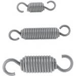
| Product name | Tension Springs - Hook Free |
|---|---|
| Part number | AUFM8-40 |
Selection criteria
Springs with machining cost can be obtained at lower price as a commercially available item.
Available sizes
■Tension Springs - Hook Free
| Material | |
|---|---|
| Main Body | Hook area |
| Spring Steel (ASTM A228) | 304 Stainless Steel |
| 304 Stainless Steel | |
■Sizes and Dimensions
| Spring O.D. | Hook pitch | Wire Dia. | Hook filament dia. | Hook I.D. | Max. load (N) (dynamic load) |
|---|---|---|---|---|---|
| 7 | 25 | 1.0 | 1.2 | 4.6 | 39.2 |
| 30 | |||||
| 35 | |||||
| 40 | |||||
| 8 | 30 | 1.2 | 1.4 | 5.2 | 66.25 |
| 35 | |||||
| 40 | |||||
| 45 | |||||
| 50 | |||||
| 60 | |||||
| 70 | |||||
| 10 | 30 | 1.4 | 1.6 | 6.8 | 86.69 |
| 35 | |||||
| 40 | |||||
| 45 | |||||
| 50 | |||||
| 60 | |||||
| 70 | |||||
| 80 | |||||
| 12 | 30 | 1.6 | 1.8 | 8.4 | 101.29 |
| 35 | |||||
| 40 | |||||
| 45 | |||||
| 50 | |||||
| 60 | |||||
| 70 | |||||
| 80 | |||||
| 90 | |||||
| 100 | |||||
| 14 | 50 | 1.8 | 2 | 10 | 107.87 |
| 60 | |||||
| 70 | |||||
| 80 | |||||
| 90 | |||||
| 100 | |||||
| 125 | |||||
| 16 | 50 | 2 | 2.6 | 11.4 | 127 |
| 60 | |||||
| 70 | |||||
| 80 | |||||
| 90 | |||||
| 100 | |||||
| 125 | |||||
| 18 | 80 | 2.3 | 2.9 | 12.9 | 180 |
| 90 | |||||
| 100 | |||||
| 125 | |||||
| 150 | |||||
| 20 | 80 | 2.6 | 3.2 | 14.2 | 230 |
| 90 | |||||
| 100 | |||||
| 125 | |||||
| 150 |
Technical Calculations
■Tension spring load calculations
P = Pi + (k x F).
P: Load (N).
Pi: Initial Tension (N).
k: Spring Constant (N/mm).
F: Deflection (mm).

Spring Anchors
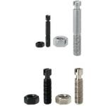
| Product name | Spring Anchors - Flat Head Screwdriver Type, with Groove |
|---|---|
| Part number | BSPO6-25 |
| Features | Posts for Tension Springs with Straight Slot Grooves available |
Selection criteria
Lead time can be shortened if excess machining is removed.
Available sizes
■Spring Anchors - Flat Head Screwdriver Type, with Groove
| Material | Surface Treatment | Accessory material |
|---|---|---|
| 1045 Carbon Steel | Black Oxide | Nut one pc (JIS Class 1) SWCH equivalent |
| 303 Stainless Steel | - | Nut one pc (JIS Class 1) 304 Stainless Steel equivalent |
■Sizes and Dimensions.
| Hex size | Mounting Height (Increments of 5 mm) | Screw Dia. (Coarse) | Thread Length | Spring Latch Shaft Dia. |
|---|---|---|---|---|
| 3 | 15-40 | M3 | 6 | φ1.8 |
| 4 | 15-40、50 | M4 | 8 | φ2 |
| 5 | 15-40、50 | M5 | 10 | φ3 |
| 6 | 15-50、60 | M6 | 12 | φ3.6 |
| 8 | 20-50、60、70 | M8 | 16 | φ5 |
| 10 | 30-50、60、70 | M10 | 20 | φ6 |
| 12 | 40,50、60、70 | M12 | 24 | φ6.5 |

-
 Terms of use of CAD data and simplified drawing data
- These terms and conditions (hereinafter referred to as “the Terms") set forth the conditions for downloading CAD data and simplified drawing data posted on https://th.misumi-ec.com/ (hereinafter referred to as the "Website") operated by MISUMI (THAILAND) CO., LTD. (hereinafter referred to as "MISUMI"). By downloading CAD data and simplified drawing data posted on the Website (hereafter referred to as “Data”), customers are deemed to have agreed to these Terms.
- 1. Purpose of Use
-
MISUMI offers the following:
1)CAD data found on the Website (3D CAD data, 3D Intermediate data and 2D CAD data) for the purpose of informing customers of the characteristics of the products offered by MISUMI or a manufacturer affiliated with MISUMI for use in their designs.
2)Simplified drawing data (in PDF format) for the purpose of checking the specifications of products. - 2. Characteristics of Data
- There may be a discrepancy in certain characteristics of products (for example: tolerance, surface roughness, chamfer, etc.) between the Data and the actual product. Furthermore, for the purpose of reducing the file size of the Data, some information such as oil groove shapes, threads, or spring shapes, may be removed from the Data.
- 3. Disclaimer
- MISUMI carefully creates the Data but makes no warranty as to the accuracy of the Data. MISUMI may at any time, and with no prior notice to customers, revise or delete Data. MISUMI assumes no responsibility for any damage or loss resulting from any revision or deletion of the Data, or any errors in said data. Customers are solely responsible for all aspects of their own designs, including those made using MISUMI’s CAD data. MISUMI may provide customers with design example data on the Website, but the quality, accuracy, functionality, safety, reliability, etc., of such data are not guaranteed. MISUMI may, at any time, and in its sole discretion, request that the customer cease its use of or destroy the Data in its possession. MISUMI may request the customer provide MISUMI documentation of such destruction.
- 4.Prohibited Acts
-
Customers or users of the Data, are prohibited from the following acts regarding the Data, in whole or in part:
(1)Requesting quotations or placing orders for products with third parties other than those authorized by MISUMI or its affiliates;
(2)Receiving quotations or orders for products from third parties by providing the Data to a third party or using the Data in their own business;
(3)Displaying links to the Website related to the Data on their own websites, etc., without MISUMI's consent;
(4)Using or reproducing the Data beyond the scope of the above-stated Purpose of Use;
(5)Modifying, altering, tampering with, translating, or adapting the Data;
(6)Selling, transferring, lending, sublicensing, or providing the Data to third parties in any way without MISUMI’s consent;
(7)Altering the content, reverse engineering, decompiling, disassembling, or analyzing the Data;
(8)Publicly disclosing or exhibiting the Data without MISUMI's consent;
(9)Using the Data for the purpose of providing products and services identical or similar to those of MISUMI;
(10)Performing acts that interfere with the proper functioning of this Website, such as acquiring Data in bulk. - 5. Copyright
-
All title and copyright in and to any information contained in the Data are owned by MISUMI or the relevant manufacturer affiliated with MISUMI and are protected by applicable copyright laws and international treaties. By downloading Data, the customer acquires no ownership rights of any kind in the intellectual property contained within. Without prior approval from MISUMI, no part of the Data may be utilized (reproduced, modified, reverse-engineered, uploaded, presented, sent, distributed, licensed, sold, or published) for any purpose other than that mentioned above.
In the event Data is found to have been to be used for any purpose other than that mentioned above or against any applicable laws, MISUMI may pursue any legal remedy available to it, which may result in forbidding the offending user from using the Data or accessing the Website. - 6. Third-Party Data
- MISUMI offers some Data provided by third parties. Such Data may be subject to separate terms and conditions, in addition to these terms. MISUMI makes no guarantee or warranty regarding Data from third parties.
- 7. Export Control
- Customers shall comply with all applicable laws and regulations regarding the export of the Data.
- 8. Amendments to the Terms
- MISUMI may, at any time, and in its sole discretion, modify these terms and conditions; any such modification will be effective immediately.
- 9. Severability
- If any term or provision of these Terms is invalid, illegal, or unenforceable in any jurisdiction, such invalidity, illegality, or unenforceability shall not affect any other term or provision of these Terms or invalidate or render unenforceable such term or provision in any other jurisdiction.
- 10.Miscellaneous
- These Terms and any disputes arising in connection therewith shall be exclusively governed by and construed in accordance with the laws of Thailand, without regard to its conflicts of law principles. The authorized courts in Thailand shall have exclusive jurisdiction to adjudicate any dispute arising in connection with these Terms.
- Revised: 16th November, 2025
CAD Download (Unit Assembly)
CAD Download: File Format
CAD Data Limitations
-
Assembly data shows the assembly drawings in the concept design phase. The sole purpose of the data is to explain the structure and functionality of the assembly and is not considered nor to be used as a final design.
You will need to edit the Data so that it meets your specific design conditions. -
Unit assembly Data consists of some sub-assemblies.
It is configured so that each sub-assembly unit can be used as it is or edited. - The Data for fabricated parts is based on easy-to-edit dimensions and shapes in sketches and histories.
- The Data including the third-part components are made by the Company.
* The part in the frame is a sub-assembly unit.
-

- * Unit assembly Data consists of some sub-assemblies.
It is configured so that each sub-assembly unit can be used as it is or edited.
Application Overview
Purpose
- Feeding sheet-like workpieces such as films using rollers.
Target workpiece
- Shape: Film, sheet
- Size: W20×t0.1mm
Design Specifications
Operating Conditions or Design Requirements
- External dimensions: W209xD110xH168mm
- Feeding speed: 300mm/s
Required Performance
- Tension: 4N
- Nip pressure:10N
Selection Criteria for Main Components
- Select a 50 W motor to feed workpieces at a tension of 4N,a nip pressure of 10N, and a seep of 300mm/s.
Design Evaluation
Verification of main components
- Select a motor that satisfies the load inertia and load torque.
- Calculation of the load inertia applied to the motor shaft.
- Conditions (values): Feeding shaft inertia JO=0.028kg・cm2, coupling inertia JC=0.028kg・cm2, feeding roller inertia JR=0.170kg・cm2
- The load inertia applied to the motor shaft, JL, is expressed by JL=JC+JO+2×JR (JL=0.028+0.028+2×0.170 =0.396kg・cm2)
- The inertia ratio, m, is expressed by m=JL/JM (m=0.396/0.045=8.8<17 times (motor specification recommendation value))
- Calculation of torque in acceleration.
- Conditions (values): Drive efficiency η=0.800, motor rotation speed N0=190.985r/min,acceleration time Tsa=0.500s,the load torque applied to the motor shaft TL=0.097N・m
- Torque in acceleration, TMa, is expressed by TMa=((((JL/η)+JM)×N0)/(9.55×104×Tsa))+TL. (TMa=((((0.396/0.800)+0.045)×190.985)/(9.55×104×0.5))+0.097=0.099N・m)
- The torque reaches its peak in acceleration. Since the rated torque is Ttyp=0.160N・m, the peak load factor Rp is
expressed by Rp=(TMa/Ttyp)×100 (Rp=(0.099/0.16)×100=61.875%) - When the effective load torque is derived from the torques of each operation pattern,
the rated torque becomes 0.096N・m<0.16N・m
Other Design Consideration
- Knurling is applied to the feeding rollers while urethane bumpers are applied to the press roller to increase the friction coefficient.
- The Nip pressure can be adjusted by changing the springs.
Explore Similar Application Examples

-

-

-

-

-

-

-

-

-

-

-

-

-

-

-

-

-

-

-

Relevant category
-

-

-

-

-

-

-

-

-

-

-

-

-

-

-

-

-

-

-

-

-

-

-

-

-

-

-

-

-

-

-

-

-

-

-

-

-

-

Relevant category
-

-

-

-

-

-

-

-

-

-

-

-

-

-

-

-

-

-

-

-

-

-

-

-

-

-

-

-

-

-

-

-

-

-

-

-

-

-

-

-

-

-

-

-

-

-

-

-

-

-

-

-

-

-

-

-

-

-

-

-

-

-

-

-

-

-


Payment Methods
- Bank
-
- Prompt Pay
-


- Cash
-

- Cash on Delivery
Social Media
MISUMI Contact
Copyright © MISUMI Corporation All Rights Reserved.