(!) Since support from Microsoft will end on January 14 2020, Windows 7 user might not be able to use MISUMI website effectively. Please consider to update your system as ‘MISUMI Website system requirement’.


- inCAD Library Home
- > No.000081 No Load Gripping Mechanism
No.000081 No Load Gripping Mechanism
19
No load gripping with a cylinder
Relevant category


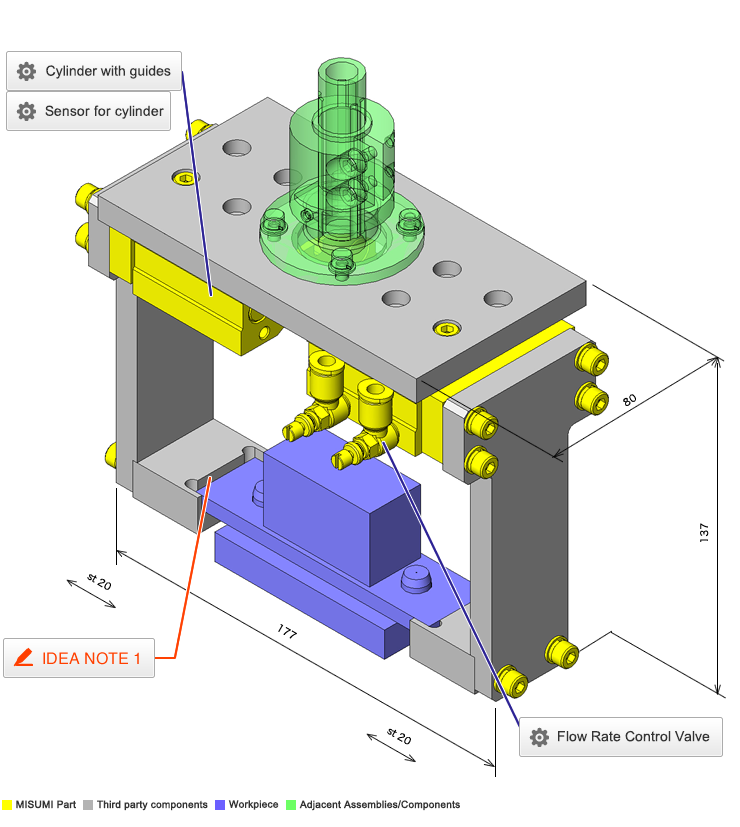
Cylinder with Guides

| Product name | Cylinders with Twin Guides? |
|---|---|
| Part number | MGCLF16-20 |
| Features | Cylinders having the guides on both ends for usability. |
Selection criteria
Guided type, size and stroke.
Available sizes
■Cylinder with Guides (Fixed stroke type)
| Bore dia. | Bearing | Slide bearing | Linear bushing bearing | Cylinder width (mm) | Overall length (Below +St) | Thickness (mm) | ||||||||||||||
|---|---|---|---|---|---|---|---|---|---|---|---|---|---|---|---|---|---|---|---|---|
| St | 10 | 20 | 25 | 30 | 40 | 50 | 75 | 100 | 10 | 20 | 25 | 30 | 40 | 50 | 75 | 100 | ||||
| φ12 | ○ | ○ | ― | ○ | ○ | ○ | ○ | ○ | ○ | ○ | ― | ○ | ○ | ○ | ○ | ○ | 56 | 39 | 22 | |
| φ16 | ○ | ○ | ― | ○ | ○ | ○ | ○ | ○ | ○ | ○ | ― | ○ | ○ | ○ | ○ | ○ | 62 | 43 | 25 | |
| φ20 | ― | ○ | ― | ○ | ○ | ○ | ○ | ○ | ○ | ○ | ― | ○ | ○ | ○ | ○ | ○ | 72 | 47 | 30 | |
| φ25 | ― | ○ | ― | ○ | ○ | ○ | ○ | ○ | ― | ○ | ― | ○ | ○ | ○ | ○ | ○ | 86 | 47.5 | 38 | |
| φ32 | ― | ― | ○ | ― | ― | ○ | ○ | ○ | ― | ― | ○ | ― | ― | ○ | ○ | ○ | 112 | 48 | ||
| φ50 | ― | ― | ○ | ― | ― | ○ | ― | ○ | ― | ― | ― | ― | ― | ― | ― | ― | 146 | 72 | 60 | |
Selection steps
■Cylinder selection steps
1, Define various load conditions
↓
2, Calculate cylinder output. (in case of double acting cylinder)
↓
3, Determine bore dia.
↓
4, Determine theoretical reference speed
↓
5, Verify cylinder's cushion mechanism
6, Verify lateral load applicable on the cylinder
Accuracy Info
■Non-rotating accuracy of guided cylinder
Non-rotating accuracy: Looseness by guide rod and bearing clearance represented in a rotation angle centered on the piston rod.
| Bore dia. | Non-rotating accuracy of tip link bar | |
|---|---|---|
| Slide bearing | Linear bushing bearing | |
| φ12 | ±0.12° | ±0.06° |
| φ16 | ±0.10° | ±0.06° |
| φ20 | ±0.09° | ±0.05° |
| φ25 | ±0.08° | ±0.05° |
| φ32 | ±0.06° | ±0.04° |
| φ50 | ±0.05° | - |
Performance info.
■Theoretical force
(N)
| Bore dia. (mm) | Operation direction | Applied pressure (MPa) | |
|---|---|---|---|
| 0.4 | 0.5 | ||
| 12 | Push side | 45 | 57 |
| Pull side | 34 | 42 | |
| 16 | Push side | 80 | 101 |
| Pull side | 60 | 75 | |
| 20 | Push side | 126 | 157 |
| Pull side | 94 | 118 | |
| 25 | Push side | 196 | 245 |
| Pull side | 151 | 189 | |
| 32 | Push side | 322 | 402 |
| Pull side | 241 | 302 | |
| 50 | Push side | 785 | 982 |
| Pull side | 660 | 825 | |
■ Allowable lateral load
(N・m)
| Bore dia. (mm) | Stroke (mm) | |||||||
|---|---|---|---|---|---|---|---|---|
| 10 | 20 | 25 | 30 | 40 | 50 | 75 | 100 | |
| 12 | 24 | 19 | ― | 16 | 14 | 12 | 37 | 31 |
| 16 | 40 | 33 | ― | 28 | 24 | 21 | 55 | 46 |
| 20 | ― | 52 | ― | 45 | 39 | 35 | 55 | 46 |
| 25 | ― | 69 | ― | 60 | 52 | 47 | 73 | 62 |
| 32 | ― | ― | 166 | ― | ― | 131 | 107 | 91 |
| 50 | ― | ― | 296 | ― | ― | 245 | ― | 241 |

Sensor for cylinder

| Product name | Sensors - For Cylinders, Grippers? |
|---|---|
| Part number | MD13L3 |
| Features | Sensors dedicated for Double Acting Cylinder |
Selection criteria
Sensors dedicated to selected cylinder
Available sizes
■Sensor for cylinder
| Cable length (m) | Sensor type | Number of leads | Lead wire exit direction |
|---|---|---|---|
| 1、3 | With contacts | 2 wires | Back |
| 1、3 | No contacts | 3 wires | |
| 1、3 | No contacts | 2 wires | |
| 1、3 | No contacts | 3 wires | Top |
| 1、3 | No contacts | 2 wires |

Flow Rate Control Valve

| Product name | Flow Rate Control Valves - 90 Deg. Elbow, Standard |
|---|---|
| Part number | SPSNL6-M5 |
| Features | Speed Controllers capable of adjusting the flow rate of compressed air. |
Selection criteria
To match selected cylinder size and to control cylinder stroke speed
Available sizes
■Flow Rate Control Valve
| Material | Control type | Color | |
|---|---|---|---|
| Black | White | ||
| Polybutylene terephthalate Threads: 304 Stainless Steel | Meter-out | ○ | ○ |
| Polybutylene terephthalate Threads: Brass | Meter-out | - | - |
| Meter-in | |||
■Sizes and Dimensions
| Bore dia. (mm) | Thread size |
|---|---|
| 4 | M5 |
| 1 | |
| 6 | M5 |
| 1 | |
| 2 | |
| 8 | 1 |
| 2 | |
| 3 | |
| 10 | 2 |
| 3 | |
| 4 | |
| 12 | 3 |
| 4 |


-
 Terms of use of CAD data and simplified drawing data
- These terms and conditions (hereinafter referred to as “the Terms") set forth the conditions for downloading CAD data and simplified drawing data posted on https://th.misumi-ec.com/ (hereinafter referred to as the "Website") operated by MISUMI (THAILAND) CO., LTD. (hereinafter referred to as "MISUMI"). By downloading CAD data and simplified drawing data posted on the Website (hereafter referred to as “Data”), customers are deemed to have agreed to these Terms.
- 1. Purpose of Use
-
MISUMI offers the following:
1)CAD data found on the Website (3D CAD data, 3D Intermediate data and 2D CAD data) for the purpose of informing customers of the characteristics of the products offered by MISUMI or a manufacturer affiliated with MISUMI for use in their designs.
2)Simplified drawing data (in PDF format) for the purpose of checking the specifications of products. - 2. Characteristics of Data
- There may be a discrepancy in certain characteristics of products (for example: tolerance, surface roughness, chamfer, etc.) between the Data and the actual product. Furthermore, for the purpose of reducing the file size of the Data, some information such as oil groove shapes, threads, or spring shapes, may be removed from the Data.
- 3. Disclaimer
- MISUMI carefully creates the Data but makes no warranty as to the accuracy of the Data. MISUMI may at any time, and with no prior notice to customers, revise or delete Data. MISUMI assumes no responsibility for any damage or loss resulting from any revision or deletion of the Data, or any errors in said data. Customers are solely responsible for all aspects of their own designs, including those made using MISUMI’s CAD data. MISUMI may provide customers with design example data on the Website, but the quality, accuracy, functionality, safety, reliability, etc., of such data are not guaranteed. MISUMI may, at any time, and in its sole discretion, request that the customer cease its use of or destroy the Data in its possession. MISUMI may request the customer provide MISUMI documentation of such destruction.
- 4.Prohibited Acts
-
Customers or users of the Data, are prohibited from the following acts regarding the Data, in whole or in part:
(1)Requesting quotations or placing orders for products with third parties other than those authorized by MISUMI or its affiliates;
(2)Receiving quotations or orders for products from third parties by providing the Data to a third party or using the Data in their own business;
(3)Displaying links to the Website related to the Data on their own websites, etc., without MISUMI's consent;
(4)Using or reproducing the Data beyond the scope of the above-stated Purpose of Use;
(5)Modifying, altering, tampering with, translating, or adapting the Data;
(6)Selling, transferring, lending, sublicensing, or providing the Data to third parties in any way without MISUMI’s consent;
(7)Altering the content, reverse engineering, decompiling, disassembling, or analyzing the Data;
(8)Publicly disclosing or exhibiting the Data without MISUMI's consent;
(9)Using the Data for the purpose of providing products and services identical or similar to those of MISUMI;
(10)Performing acts that interfere with the proper functioning of this Website, such as acquiring Data in bulk. - 5. Copyright
-
All title and copyright in and to any information contained in the Data are owned by MISUMI or the relevant manufacturer affiliated with MISUMI and are protected by applicable copyright laws and international treaties. By downloading Data, the customer acquires no ownership rights of any kind in the intellectual property contained within. Without prior approval from MISUMI, no part of the Data may be utilized (reproduced, modified, reverse-engineered, uploaded, presented, sent, distributed, licensed, sold, or published) for any purpose other than that mentioned above.
In the event Data is found to have been to be used for any purpose other than that mentioned above or against any applicable laws, MISUMI may pursue any legal remedy available to it, which may result in forbidding the offending user from using the Data or accessing the Website. - 6. Third-Party Data
- MISUMI offers some Data provided by third parties. Such Data may be subject to separate terms and conditions, in addition to these terms. MISUMI makes no guarantee or warranty regarding Data from third parties.
- 7. Export Control
- Customers shall comply with all applicable laws and regulations regarding the export of the Data.
- 8. Amendments to the Terms
- MISUMI may, at any time, and in its sole discretion, modify these terms and conditions; any such modification will be effective immediately.
- 9. Severability
- If any term or provision of these Terms is invalid, illegal, or unenforceable in any jurisdiction, such invalidity, illegality, or unenforceability shall not affect any other term or provision of these Terms or invalidate or render unenforceable such term or provision in any other jurisdiction.
- 10.Miscellaneous
- These Terms and any disputes arising in connection therewith shall be exclusively governed by and construed in accordance with the laws of Thailand, without regard to its conflicts of law principles. The authorized courts in Thailand shall have exclusive jurisdiction to adjudicate any dispute arising in connection with these Terms.
- Revised: 16th November, 2025
CAD Download (Unit Assembly)
CAD Download: File Format
CAD Data Limitations
-
Assembly data shows the assembly drawings in the concept design phase. The sole purpose of the data is to explain the structure and functionality of the assembly and is not considered nor to be used as a final design.
You will need to edit the Data so that it meets your specific design conditions. -
Unit assembly Data consists of some sub-assemblies.
It is configured so that each sub-assembly unit can be used as it is or edited. - The Data for fabricated parts is based on easy-to-edit dimensions and shapes in sketches and histories.
- The Data including the third-part components are made by the Company.
* The part in the frame is a sub-assembly unit.
-

- * Unit assembly Data consists of some sub-assemblies.
It is configured so that each sub-assembly unit can be used as it is or edited.
Application Overview
Purpose
- Gripper mechanism that lifts workpiece without transferring load from lifting cylinder.
Points for use
- Gripping the workpiece is done using guided cylinder.
- Since workpiece is loosely held inside gripper fingers this design is not recommended in applications that require high positioning accuracy.
Target workpiece
- Molded plastic assembly
External dims.: W110 x D40 x H88mm
Workpiece weight: 167g
Design Specifications
Operating Conditions or Design Requirements
- External dimensions: W217 x D80 x H137mm (When workpiece released)
- Cylinder stroke: 20mm
Required Performance
- Cylinder stroke tolerance: +1.5mm MAX.
Selection Criteria for Main Components
- Cylinder
- A cylinder with adequate stroke for the workpiece is selected.
- Gripping unit is mounted at the end of the robot arm, for space saving purpose low profile cylinders are selected.
Design Evaluation
Verification of main components
- Calculation not required since no load applies to the cylinder.
Other Design Consideration
- When holding the workpiece, use a wide surface for stability.
- Design should allow some clearance (~2mm) between gripping fingers and workpiece to compensate for cylinder stroke tolerance.
Explore Similar Application Examples

-

-

-

-

-

-

-

-

-

-

-

-

-

-

-

-

-

-

-

-

-

Relevant category
-

-

-

-

-

-

-

-

-

-

-

-

-

-

-

-

-

-

-

-

-

-

-

-

-

-

-

-

-

-

-

-

-

-

-

-

Relevant category
-

-

-

-

-

-

-

-

-

-

-

-

-

-

-

-

-

-

-

-

-

-

-

-

-

-

-

-

-

-

-

-

-

-

-

-

-

-

-

-

-

-

-

-

-

-

-

-

-

-

-

-

-

-

-


Payment Methods
- Bank
-
- Prompt Pay
-


- Cash
-

- Cash on Delivery
Social Media
MISUMI Contact
Copyright © MISUMI Corporation All Rights Reserved.