(!) Since support from Microsoft will end on January 14 2020, Windows 7 user might not be able to use MISUMI website effectively. Please consider to update your system as ‘MISUMI Website system requirement’.


- inCAD Library Home
- > No.000122 Air Blow Mechanism
No.000122 Air Blow Mechanism
84
An air blow device that blows air from all directions.
Relevant category


Adjusting Hose

| Product name | Adjustable Hoses - Standard / L-Shaped / Branch |
|---|---|
| Part number | HOSVA3-0-3-A1 |
| Features | Adjusting Hoses which can be bent to a right angle at an arbitrary portion |
Selection criteria
Suitable for changing the air blow direction freely.
Risk info.
Confirm that the required flow velocity has been secured.
Available sizes
■Adjustable Hoses - Standard / L-Shaped / Branch
| Connector | Hose Nominal | Hose Color | Number of links | Connector Thread Size (PT) | |
|---|---|---|---|---|---|
| Threaded (select) | Male Valve / Female Valve (fixed) | ||||
| Threaded | 2 | Blue | 0-30 | 1(R1/8) 2(R1/4) | 2(R/Rc1/4) |
| Gray | |||||
| Black | |||||
| Male Valve | 3 | Blue | 3(R3/8) | 3(R/Rc3/8) | |
| 4(R1/2) | |||||
| Female Valve | 4 | Gray | 3(R3/8) | 4(R/Rc1/2) | |
| 4(R1/2) | |||||
■Nozzle Shape.

■Shape A.
| Hose Nominal | A1 | A2 | A3 | |||||||||||||||
|---|---|---|---|---|---|---|---|---|---|---|---|---|---|---|---|---|---|---|
| C | C1 | D | d1 | d2 | d3 | C | C1 | D | d1 | d2 | d3 | C | C1 | D | d1 | d2 | d3 | |
| 2 | 30.0 | 16.0 | 16.0 | 1.6 | 4.9 | 7.0 | 30.0 | 19.0 | 16.0 | 3.2 | 6.3 | 9.6 | 35.0 | 25.5 | 16.0 | 6.3 | 9.5 | 11.0 |
| 3 | 33.0 | 19.0 | 21.0 | 6.3 | 9.5 | 13.0 | 39.0 | 28.0 | 21.0 | 9.5 | 13.0 | 15.0 | 33.0 | 22.0 | 21.0 | 12.7 | 15.0 | 16.0 |
| 4 | 37.5 | 24.5 | 24.5 | 6.6 | 10.5 | 12.5 | 37.5 | 24.5 | 24.5 | 9.5 | 12.5 | 15.5 | 37.5 | 24.5 | 24.5 | 12.5 | 17.0 | 19.0 |
■Shape B.
| Hose Nominal | B1 | B2 | B3 | ||||||||||||
|---|---|---|---|---|---|---|---|---|---|---|---|---|---|---|---|
| C | C1 | D | d1 | d2 | C | C1 | D | d1 | d2 | C | C1 | D | d1 | d2 | |
| 2 | 24.5 | 12.0 | 16.0 | 1.8 | 4.1 | 25.5 | 12.0 | 16.0 | 3.2 | 5.6 | 26.3 | 12.0 | 16.0 | 6.3 | 9.0 |
| 4 | 36.0 | 20.0 | 24.5 | 6.8 | 9.5 | 37.0 | 18.0 | 24.5 | 9.5 | 12.4 | 39.0 | 19.5 | 24.5 | 12.4 | 15.4 |
■Shape C.
| Hose Nominal | C1 | C2 | ||
|---|---|---|---|---|
| d1 | F1 | d1 | F1 | |
| 2 | 1.0 | 41.0 | 1.5 | 41.0 |
■Shape D.
| Hose Nominal | D1 | |||||
|---|---|---|---|---|---|---|
| C | D | d1 | d2 | d3 | d4 | |
| 2 | 26.4 | 16 | 3.2 | 1.7 | 25.4 | 26.8 |
| 3 | 39 | 22 | 5 | 3 | 32 | 34 |
| 4 | 50.5 | 25.0 | 6 | 4.5 | 44.5 | 48 |
■Shape M.
| Hose Nominal | M1 | M2 | ||||||||
|---|---|---|---|---|---|---|---|---|---|---|
| A | L | (H) | T | Rc(PT) | A | L | (H) | T | Rc(PT) | |
| 2 | 18.5 | 21 | 14 | 14 | Rc1/8 | 22.5 | 25 | 17 | 10 | Rc1/4 |
Unit(mm)
Performance info.
■Speeds / Loads (Load Info.) of Adjusting Hose.
■Withstanding Pressure.
| Hose Nominal | Withstanding Pressure MPa | |
|---|---|---|
| Fluid | Air | |
| 2 | 0.2 | 0.5 |
| 3 | 0.2 | 0.5 |
| 4 | 0.2 | 0.5 |
■Chemical Resistance.
| Chemical Name | A / NA |
|---|---|
| Solvent | ○ |
| Lubricant | ○ |
| Water | ○ |
| Acid | × |
| Alkali | × |

Leveling Mount & Plate with Caster Unit
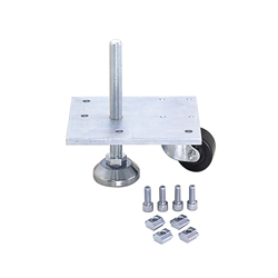
| Product name | Leveling Mount & Plate - with Caster Unit |
|---|---|
| Part number | HAJCHP6 |
| Features | Mounting Units for Casters / Leveling Mounts for Aluminum Extrusions. |
Selection criteria
The design exclusively for aluminum extrusion allows for appropriate mounting.
Available sizes
■Leveling Mount & Plate - with Caster Unit
| Aluminum extrusion sizes | Caster types | Plate Dimensions (mm) |
|---|---|---|
| □20 | Dual Wheel Swivel Type | 135x75xt6 |
| □40 | Low Profile Swivel | 100x125xt9 |
| □30 | Dual Wheel Swivel Type | 135x75xt6 |
| □40・□45 | Low Profile Swivel | 166x125xt9 |
| □50 | 166x125xt9 | |
| □60 | 125x125xt9 | |
| □80 | Medium Load Type | 150x150xt12 |
| □90 | 165x165xt12 |
Performance info.
■Speeds / Loads (Load Info.) of Leveling Mount + Plate with Caster Unit.
| Aluminum extrusion sizes | Caster Allowable Load kN (kgf) | Leveling Mount Allowable Load kN (kgf) |
|---|---|---|
| □20 | 0.9(100) | 4.9(500) |
| □40 | 1.4(150) | 16.6(1700) |
| □30 | 4.9(500) | |
| □40・□45 | 16.6(1700) | |
| □50 | 1.7(170) | |
| □60 | 1.4(150) | |
| □80 | 2.9(300) | 39.2(4000) |
| □90 |

Gasket
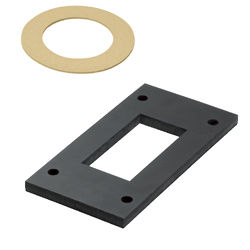
| Product name | Rubber/Sponge Packings |
|---|---|
| Part number | FRC4A2-A120-V49-Q95-N15 |
Selection criteria
Select to prevent air leakage and to enhance the efficiency.
Available sizes
■Rubber/Sponge Packings
| Material | Hardness | Color |
|---|---|---|
| Nitrile Rubber | Shore A70 | Black |
| Chloroprene Rubber | Shore A65 | Black |
| Amber Color Rubber | Shore A45 | Amber Color |
| Silicon Rubber | Shore A70 | Light Gray |
| Silicon Rubber | Shore A50 | Milky White |
| Fluororubber | Shore A80 | Black |
| Chloroprene Rubber Sponge | Asker C25 | Black |
| Fluororubber Sponge | Asker C35 | Black |
| Silicon Rubber Sponge | Asker C35 | Orange |
| Ethylene Rubber | Shore A65 | Black |
■Sizes and Dimensions.
| Thickness(mm) | Configure in 1mm increments(Vertical ≧ Horizontal ≧ Thickness) | 0.5mm Increment | ||
|---|---|---|---|---|
| Rubber | Sponge | Vertical(mm) | Horizontal(mm) | Hole Dia.(mm) |
| 1 | 3 5 10 | 25 - 500 (when thickness = 30, vertical ≧ 30) | 25 - 500 (when thickness = 30, horizontal ≧ 30) | 3-30 |
| 2 | ||||
| 3 | ||||
| 5 | ||||
| 10 | ||||
| 15 | ||||
| 20 | ||||
| 30 | ||||

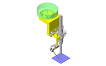
IDEA NOTE Air blow from all directions
Due to air discharge nozzles arranged above, below and on the right and left of a workpiece, air is blown from all directions.


-
 Terms of use of CAD data and simplified drawing data
- These terms and conditions (hereinafter referred to as “the Terms") set forth the conditions for downloading CAD data and simplified drawing data posted on https://th.misumi-ec.com/ (hereinafter referred to as the "Website") operated by MISUMI (THAILAND) CO., LTD. (hereinafter referred to as "MISUMI"). By downloading CAD data and simplified drawing data posted on the Website (hereafter referred to as “Data”), customers are deemed to have agreed to these Terms.
- 1. Purpose of Use
-
MISUMI offers the following:
1)CAD data found on the Website (3D CAD data, 3D Intermediate data and 2D CAD data) for the purpose of informing customers of the characteristics of the products offered by MISUMI or a manufacturer affiliated with MISUMI for use in their designs.
2)Simplified drawing data (in PDF format) for the purpose of checking the specifications of products. - 2. Characteristics of Data
- There may be a discrepancy in certain characteristics of products (for example: tolerance, surface roughness, chamfer, etc.) between the Data and the actual product. Furthermore, for the purpose of reducing the file size of the Data, some information such as oil groove shapes, threads, or spring shapes, may be removed from the Data.
- 3. Disclaimer
- MISUMI carefully creates the Data but makes no warranty as to the accuracy of the Data. MISUMI may at any time, and with no prior notice to customers, revise or delete Data. MISUMI assumes no responsibility for any damage or loss resulting from any revision or deletion of the Data, or any errors in said data. Customers are solely responsible for all aspects of their own designs, including those made using MISUMI’s CAD data. MISUMI may provide customers with design example data on the Website, but the quality, accuracy, functionality, safety, reliability, etc., of such data are not guaranteed. MISUMI may, at any time, and in its sole discretion, request that the customer cease its use of or destroy the Data in its possession. MISUMI may request the customer provide MISUMI documentation of such destruction.
- 4.Prohibited Acts
-
Customers or users of the Data, are prohibited from the following acts regarding the Data, in whole or in part:
(1)Requesting quotations or placing orders for products with third parties other than those authorized by MISUMI or its affiliates;
(2)Receiving quotations or orders for products from third parties by providing the Data to a third party or using the Data in their own business;
(3)Displaying links to the Website related to the Data on their own websites, etc., without MISUMI's consent;
(4)Using or reproducing the Data beyond the scope of the above-stated Purpose of Use;
(5)Modifying, altering, tampering with, translating, or adapting the Data;
(6)Selling, transferring, lending, sublicensing, or providing the Data to third parties in any way without MISUMI’s consent;
(7)Altering the content, reverse engineering, decompiling, disassembling, or analyzing the Data;
(8)Publicly disclosing or exhibiting the Data without MISUMI's consent;
(9)Using the Data for the purpose of providing products and services identical or similar to those of MISUMI;
(10)Performing acts that interfere with the proper functioning of this Website, such as acquiring Data in bulk. - 5. Copyright
-
All title and copyright in and to any information contained in the Data are owned by MISUMI or the relevant manufacturer affiliated with MISUMI and are protected by applicable copyright laws and international treaties. By downloading Data, the customer acquires no ownership rights of any kind in the intellectual property contained within. Without prior approval from MISUMI, no part of the Data may be utilized (reproduced, modified, reverse-engineered, uploaded, presented, sent, distributed, licensed, sold, or published) for any purpose other than that mentioned above.
In the event Data is found to have been to be used for any purpose other than that mentioned above or against any applicable laws, MISUMI may pursue any legal remedy available to it, which may result in forbidding the offending user from using the Data or accessing the Website. - 6. Third-Party Data
- MISUMI offers some Data provided by third parties. Such Data may be subject to separate terms and conditions, in addition to these terms. MISUMI makes no guarantee or warranty regarding Data from third parties.
- 7. Export Control
- Customers shall comply with all applicable laws and regulations regarding the export of the Data.
- 8. Amendments to the Terms
- MISUMI may, at any time, and in its sole discretion, modify these terms and conditions; any such modification will be effective immediately.
- 9. Severability
- If any term or provision of these Terms is invalid, illegal, or unenforceable in any jurisdiction, such invalidity, illegality, or unenforceability shall not affect any other term or provision of these Terms or invalidate or render unenforceable such term or provision in any other jurisdiction.
- 10.Miscellaneous
- These Terms and any disputes arising in connection therewith shall be exclusively governed by and construed in accordance with the laws of Thailand, without regard to its conflicts of law principles. The authorized courts in Thailand shall have exclusive jurisdiction to adjudicate any dispute arising in connection with these Terms.
- Revised: 16th November, 2025
CAD Download (Unit Assembly)
CAD Download: File Format
CAD Data Limitations
-
Assembly data shows the assembly drawings in the concept design phase. The sole purpose of the data is to explain the structure and functionality of the assembly and is not considered nor to be used as a final design.
You will need to edit the Data so that it meets your specific design conditions. -
Unit assembly Data consists of some sub-assemblies.
It is configured so that each sub-assembly unit can be used as it is or edited. - The Data for fabricated parts is based on easy-to-edit dimensions and shapes in sketches and histories.
- The Data including the third-part components are made by the Company.
* The part in the frame is a sub-assembly unit.
-

- * Unit assembly Data consists of some sub-assemblies.
It is configured so that each sub-assembly unit can be used as it is or edited.
Application Overview
Purpose
- A structure in which dust is removed from a workpiece utilizing ring blower from all directions while the workpiece is transferred by a conveyor.
Points for use
- Workpiece is automatically moved onto the conveyor using a pusher from previous station.
- At air blow station cover is used to prevent dust from contaminating surrounding areas.
Target workpiece
- Bottle in bowling pin shape (resin).
- Outer dimensions: D200 x H340mm.
- Workpiece weight: 570g.
- Workpiece volume: 0.0065 m³ -> 6.5L.
Design Specifications
Operating Conditions or Design Requirements
- Outer dimensions: W608 x D628 x H1376mm.
- Conveyor length: 595mm.
- Conveyor roller strength: 273N.
Required Performance
- Ring blower air discharge amount: 2.5m³/min at maximum.
- Air volume discharged from one nozzle: 0.0694m³/min.
- Air speed discharged from one nozzle: 37.11m/s.
Selection Criteria for Main Components
- Conveyor.
- A conveyor that can withstand the weight of workpieces filled with water is selected.
- Workpiece weight 5.7N + water 65N = 70.7N < conveyor roller strength 273N.
- Nozzle (adjusting hose).
- Two types of nozzles with different hose lengths are selected so that the entire surface of the workpiece is blown.
- Ring blower.
- A ring blower is selected to address the number of nozzles.
Design Evaluation
Verification of main components
- [Air speed is verified based on the air volume per nozzle.]
- [Air volume<per nozzle>.]
- Air volume = ring blower air discharge amount/number of nozzles = 0.0694m³/min.
- [Air speed<per nozzle>.]
- From the nozzle outlet diameter of φ6.3mm, the nozzle outlet sectional area is,
sectional area = (3.15 x 10⁻³)² x π = 3.117 x 10⁻⁵m². - Air speed = air volume/(nozzle outlet sectional area x 60)
=0.0694/(3.117x10⁻⁵×60)=37.11m/s.
- From the nozzle outlet diameter of φ6.3mm, the nozzle outlet sectional area is,
Other Design Consideration
- Adjusting hoses are used so that the air blow directions can be adjusted on site.
Explore Similar Application Examples

-

-

-

-

-

-

-

-

-

-

-

-

-

-

-

-

-

-

-

Relevant category
-

-

-

-

-

-

-

-

-

-

-

-

-

-

-
-

-

-

-

-

-

-

-

-

-

-

-

-

-

-

-

-

-

-

-

Relevant category
-

-

-

-

-

-

-

-

-

-

-

-

-

-

-

-

-

-

-

-

-

-

-

-

-

-

-

-

-

-

-

-

-

-

-

-

-

-

-

-

-

-

-

-

-

-

-

-

-

-

-

-

-

-

-

-


Payment Methods
- Bank
-
- Prompt Pay
-


- Cash
-

- Cash on Delivery
Social Media
MISUMI Contact
Copyright © MISUMI Corporation All Rights Reserved.