(!) Since support from Microsoft will end on January 14 2020, Windows 7 user might not be able to use MISUMI website effectively. Please consider to update your system as ‘MISUMI Website system requirement’.


- inCAD Library Home
- > No.000194 Rotary Inspection Station
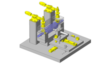
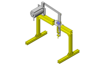
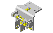
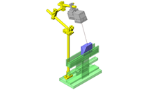
No.000194 Rotary Inspection Station
12
Rotary unit for visual inspection of workpiece.
Relevant category


Deep Groove Ball Bearings
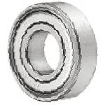
| Product name | Deep Groove Ball Bearings - Economy, Double Shielded |
|---|---|
| Part number | C6903ZZ |
| Features | Major overseas manufacturers' bearings equivalent to the domestic products in product quality. Please place order for these products if a large lot of bearings are required. |
Selection criteria
Use it for the rotary shaft bearing which is the main part of the equipment.
Available sizes
■Deep Groove Ball Bearings - Economy, Double Shielded
Material: 52100 Bearing Steel
| (Name No.) | Shaft Bore Dia. | O.D. | Thickness |
|---|---|---|---|
| C6900ZZ | φ10 | φ22 | 6 |
| C6000ZZ | φ26 | 8 | |
| C6200ZZ | φ30 | 9 | |
| C6300ZZ | φ35 | 11 | |
| C6901ZZ | φ12 | φ24 | 6 |
| C6001ZZ | φ28 | 8 | |
| C6201ZZ | φ32 | 10 | |
| C6301ZZ | φ37 | 12 | |
| C6902ZZ | φ15 | φ28 | 7 |
| C6002ZZ | φ32 | 9 | |
| C6202ZZ | φ35 | 11 | |
| C6302ZZ | φ42 | 13 | |
| C6903ZZ | φ17 | φ30 | 7 |
| C6003ZZ | φ35 | 10 | |
| C6203ZZ | φ40 | 12 | |
| C6303ZZ | φ47 | 14 | |
| C6904ZZ | φ20 | φ37 | 9 |
| C6004ZZ | φ42 | 12 | |
| C6204ZZ | φ47 | 14 | |
| C6304ZZ | φ52 | 15 | |
| C6905ZZ | φ25 | φ42 | 9 |
| C6005ZZ | φ47 | 12 | |
| C6205ZZ | φ52 | 15 | |
| C6305ZZ | φ62 | 17 | |
| C6906ZZ | φ30 | φ47 | 9 |
| C6006ZZ | φ55 | 13 | |
| C6206ZZ | φ62 | 16 | |
| C6306ZZ | φ72 | 19 |
* Please see the product pages for recommended dimensions of the mating shaft.
Performance info.
■Load info of the Deep Groove Ball Bearings - Economy Type, Double Shielded
| (Name No.) | Shaft Bore Dia. | O.D. | Basic Load Rating | Allowable Rotational Speed rpm (Reference) | |
|---|---|---|---|---|---|
| Cr (Dynamic) N | Cor (Static) N | ||||
| C6900ZZ | φ10 | φ22 | 2.7 | 1.27 | 30000 |
| C6000ZZ | φ26 | 4.55 | 1.97 | 29000 | |
| C6200ZZ | φ30 | 5.1 | 2.39 | 25000 | |
| C6300ZZ | φ35 | 8.2 | 3.5 | 23000 | |
| C6901ZZ | φ12 | φ24 | 2.89 | 1.46 | 27000 |
| C6001ZZ | φ28 | 5.1 | 2.39 | 26000 | |
| C6201ZZ | φ32 | 6.8 | 3.05 | 22000 | |
| C6301ZZ | φ37 | 9.7 | 4.2 | 20000 | |
| C6902ZZ | φ15 | φ28 | 3.65 | 2 | 24000 |
| C6002ZZ | φ32 | 5.6 | 2.83 | 22000 | |
| C6202ZZ | φ35 | 7.75 | 3.6 | 19000 | |
| C6302ZZ | φ42 | 11.4 | 5.45 | 17000 | |
| C6903ZZ | φ17 | φ30 | 4.65 | 2.58 | 22000 |
| C6003ZZ | φ35 | 6.8 | 3.35 | 20000 | |
| C6203ZZ | φ40 | 9.6 | 4.6 | 18000 | |
| C6303ZZ | φ47 | 13.5 | 6.55 | 16000 | |
| C6904ZZ | φ20 | φ37 | 6.4 | 3.7 | 19000 |
| C6004ZZ | φ42 | 9.4 | 5.05 | 18000 | |
| C6204ZZ | φ47 | 12.8 | 6.6 | 16000 | |
| C6304ZZ | φ52 | 15.9 | 7.9 | 14000 | |
| C6905ZZ | φ25 | φ42 | 7.05 | 4.55 | 16000 |
| C6005ZZ | φ47 | 10.1 | 5.85 | 15000 | |
| C6205ZZ | φ52 | 14 | 7.85 | 13900 | |
| C6305ZZ | φ62 | 21.2 | 10.9 | 12000 | |
| C6906ZZ | φ30 | φ47 | 7.25 | 5 | 14000 |
| C6006ZZ | φ55 | 13.2 | 8.3 | 13000 | |
| C6206ZZ | φ62 | 19.5 | 11.3 | 11000 | |
| C6306ZZ | φ72 | 26.7 | 15 | 10000 | |

Shaft Collar

| Product name | Shaft Collars - 2 Tapped Holes |
|---|---|
| Part number | PSCSW20-10 |
Selection criteria
Easy-to-assemble parts with a pre-inserted tap
Available sizes
■Shaft Collars - 2 Tapped Holes
| Material | Surface Treatment | Accessory |
|---|---|---|
| 1045 Carbon Steel | Black Oxide | Hex Socket Head Cap Screw 1 pcs. |
| Electroless Nickel Plating | Hex Socket Head Cap Screw 1 pcs. (SUS) | |
| 304 Stainless Steel | − |
■Sizes and Dimensions
| Shaft Bore Dia. | Overall width (Thickness) | O.D. | Fastening Screw Dia. (Coarse) | Mounting screw DIA. (Coarse) |
|---|---|---|---|---|
| φ6 | 8 | φ20 | M3 | M3 |
| 10 | M4 | |||
| φ8 | 8 | φ25 | M3 | |
| 10 | M4 | M4 | ||
| 12 | φ30 | M5 | M5 | |
| φ10 | 8 | M3 | M5 | |
| 10 | M4 | |||
| 12 | M5 | |||
| φ12 | 8 | M3 | M5 | |
| 10 | M4 | |||
| 12 | M5 | |||
| 15 | φ35 | M6 | M6 | |
| φ13 | 10 | φ30 | M4 | M4 |
| 12 | φ34 | M5 | M5 | |
| φ15 | 10 | M4 | M4 | |
| 12 | φ35 | M5 | M5 | |
| 15 | φ40 | M6 | M6 | |
| φ16 | 10 | φ35 | M5 | M4 |
| 12 | M5 | |||
| 15 | φ40 | M6 | M6 | |
| φ18・φ20 | 10 | M5 | M4 | |
| 12 | M5 | |||
| 15 | φ45 | M6 | M6 | |
| φ25 | 12 | M5 | M5 | |
| 15 | φ50 | M6 | M6 | |
| φ30 | 15 | φ55 | M6 |
Accuracy Info
■Accuracy of the Shaft Collars - Slit 2-tapped Type
Shaft Bore Dia. Tolerance: +0.05/+0.01
O.D. Tolerance: ±0.1
Overall Width Tolerance: ±0.1
Perpendicularity of the Mounting Surface and the Shaft Bore: 0.02 or less

Workpiece Guides - Straight

| Product name | Guides- Straight |
|---|---|
| Part number | WGHNC-17-10-10 |
Selection criteria
Economical workpiece securing material.
Available sizes
■Guides- Straight
| Material | Surface Treatment |
|---|---|
| 1045 Carbon Steel | Black Oxide |
| Electroless Nickel Plating | |
| 304 Stainless Steel | - |
| Polyacetal | |
| MC Nylon |
■Sizes and Dimensions
| Width | Thickness | Height (1 mm Increments) | Applicable Mounting Bolt Dia. | ||
|---|---|---|---|---|---|
| 17 | 20 | 30 | |||
| ○ | ○ | 10 | 6~10 | M3 | |
| ○ | ○ | 12 | |||

IDEA NOTE How to create a simple mechanism for visual inspection?
Utilize bearings and tapped shaft collar to create a simple turntable type rotary mechanism.

-
 Terms of use of CAD data and simplified drawing data
- These terms and conditions (hereinafter referred to as “the Terms") set forth the conditions for downloading CAD data and simplified drawing data posted on https://th.misumi-ec.com/ (hereinafter referred to as the "Website") operated by MISUMI (THAILAND) CO., LTD. (hereinafter referred to as "MISUMI"). By downloading CAD data and simplified drawing data posted on the Website (hereafter referred to as “Data”), customers are deemed to have agreed to these Terms.
- 1. Purpose of Use
-
MISUMI offers the following:
1)CAD data found on the Website (3D CAD data, 3D Intermediate data and 2D CAD data) for the purpose of informing customers of the characteristics of the products offered by MISUMI or a manufacturer affiliated with MISUMI for use in their designs.
2)Simplified drawing data (in PDF format) for the purpose of checking the specifications of products. - 2. Characteristics of Data
- There may be a discrepancy in certain characteristics of products (for example: tolerance, surface roughness, chamfer, etc.) between the Data and the actual product. Furthermore, for the purpose of reducing the file size of the Data, some information such as oil groove shapes, threads, or spring shapes, may be removed from the Data.
- 3. Disclaimer
- MISUMI carefully creates the Data but makes no warranty as to the accuracy of the Data. MISUMI may at any time, and with no prior notice to customers, revise or delete Data. MISUMI assumes no responsibility for any damage or loss resulting from any revision or deletion of the Data, or any errors in said data. Customers are solely responsible for all aspects of their own designs, including those made using MISUMI’s CAD data. MISUMI may provide customers with design example data on the Website, but the quality, accuracy, functionality, safety, reliability, etc., of such data are not guaranteed. MISUMI may, at any time, and in its sole discretion, request that the customer cease its use of or destroy the Data in its possession. MISUMI may request the customer provide MISUMI documentation of such destruction.
- 4.Prohibited Acts
-
Customers or users of the Data, are prohibited from the following acts regarding the Data, in whole or in part:
(1)Requesting quotations or placing orders for products with third parties other than those authorized by MISUMI or its affiliates;
(2)Receiving quotations or orders for products from third parties by providing the Data to a third party or using the Data in their own business;
(3)Displaying links to the Website related to the Data on their own websites, etc., without MISUMI's consent;
(4)Using or reproducing the Data beyond the scope of the above-stated Purpose of Use;
(5)Modifying, altering, tampering with, translating, or adapting the Data;
(6)Selling, transferring, lending, sublicensing, or providing the Data to third parties in any way without MISUMI’s consent;
(7)Altering the content, reverse engineering, decompiling, disassembling, or analyzing the Data;
(8)Publicly disclosing or exhibiting the Data without MISUMI's consent;
(9)Using the Data for the purpose of providing products and services identical or similar to those of MISUMI;
(10)Performing acts that interfere with the proper functioning of this Website, such as acquiring Data in bulk. - 5. Copyright
-
All title and copyright in and to any information contained in the Data are owned by MISUMI or the relevant manufacturer affiliated with MISUMI and are protected by applicable copyright laws and international treaties. By downloading Data, the customer acquires no ownership rights of any kind in the intellectual property contained within. Without prior approval from MISUMI, no part of the Data may be utilized (reproduced, modified, reverse-engineered, uploaded, presented, sent, distributed, licensed, sold, or published) for any purpose other than that mentioned above.
In the event Data is found to have been to be used for any purpose other than that mentioned above or against any applicable laws, MISUMI may pursue any legal remedy available to it, which may result in forbidding the offending user from using the Data or accessing the Website. - 6. Third-Party Data
- MISUMI offers some Data provided by third parties. Such Data may be subject to separate terms and conditions, in addition to these terms. MISUMI makes no guarantee or warranty regarding Data from third parties.
- 7. Export Control
- Customers shall comply with all applicable laws and regulations regarding the export of the Data.
- 8. Amendments to the Terms
- MISUMI may, at any time, and in its sole discretion, modify these terms and conditions; any such modification will be effective immediately.
- 9. Severability
- If any term or provision of these Terms is invalid, illegal, or unenforceable in any jurisdiction, such invalidity, illegality, or unenforceability shall not affect any other term or provision of these Terms or invalidate or render unenforceable such term or provision in any other jurisdiction.
- 10.Miscellaneous
- These Terms and any disputes arising in connection therewith shall be exclusively governed by and construed in accordance with the laws of Thailand, without regard to its conflicts of law principles. The authorized courts in Thailand shall have exclusive jurisdiction to adjudicate any dispute arising in connection with these Terms.
- Revised: 16th November, 2025
CAD Download (Unit Assembly)
CAD Download: File Format
CAD Data Limitations
-
Assembly data shows the assembly drawings in the concept design phase. The sole purpose of the data is to explain the structure and functionality of the assembly and is not considered nor to be used as a final design.
You will need to edit the Data so that it meets your specific design conditions. -
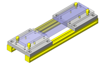
Unit assembly Data consists of some sub-assemblies.
It is configured so that each sub-assembly unit can be used as it is or edited. - The Data for fabricated parts is based on easy-to-edit dimensions and shapes in sketches and histories.
- The Data including the third-part components are made by the Company.
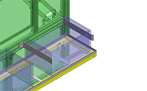
* The part in the frame is a sub-assembly unit.
-

- * Unit assembly Data consists of some sub-assemblies.
It is configured so that each sub-assembly unit can be used as it is or edited.
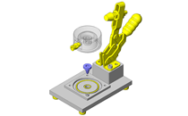
Application Overview
Purpose
- Assist visual inspection of workpiece carried over by conveyor. Rotary mechanism is driven by a motor stationed at the inspection point.
Target workpiece
- Shape: plastic plate
- Size: W 65 x D 8 x H 130 mm
- Weight: 150 g
Design Specifications
Operating Conditions or Design Requirements
- Rotational speed at inspection: 12 rpm
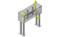
- External size: φ 90 x H 80 mm
Required Performance
- Position repeatability: ± 0.3 mm
Selection criteria for Main Components
- Rotational speed of the workpiece: 12 rpm, O.D. of rotary pallet: φ 90 mm Select bearings with a size having a margin fitting this dimension.
Design Evaluation
Verification of main components
- Verify bearing durability for the load condition.
- Check the life of bearing
- Conditional values: bearings:
Basic dynamic load rating of C6903ZZ: Cr = 4.65 kN = 4650 N, - Workpiece weight: M1 = 150 g = 0.15 kg,
- Component weight borne by the bearing of the rotary pallet: M2 = 400 g = 0.4 kg,
- Gravitational acceleration = 9.8 m/s².
- Let radial dynamic equivalent load be Pr, radial load Fr, thrust load Fa, radial factor X = 1, and thrust factor Y = 2.3 , then,
- Only the thrust load will be applied to the bearing by the workpiece and component. Assuming that radial load Fr = 0 N, We obtain the following: Fa = (M1 + M2) × g = (0.15 + 0.4) × 9.8 = 5.4 N,
- Pr=X×Fr+Y×Fa=1×0+2.3×5.4=12.4[N].
- Rated life (10⁶ rotations): L = (Cr/Pr)³ = (4650/12.4)³ = 52.7×10⁶ (10⁶ rotations) = 52.7 (10¹² rotations) Thus, there exists sufficient margin.
- Conditional values: bearings:
Other Design Consideration
- Be careful during the inspection process as the workpiece may fall off the grip. Therefore, implement additional workpiece securing mechanisms as necessary.
Explore Similar Application Examples

-
-

-
-

-

-
Relevant category
-
-

-

-

-

-

-

-

-

-

-

-

-

-

-

-

-

-

-

-

Relevant category
-
-

-

-

-

-

-

-
Relevant category
-

-

-

-

-

-

-

-

-

-

-

-

-

-
-

-

-

-

-

-

-

-

-

-

-

-

-

-

-

-

-

-

-

-

-

-

Relevant category
-

-

-

-

-

-

-

-

-

-

-

-

-

-

-

-

-

-

-
-

-

-

-

-

-

-

-

-

-

-

-

-

-

-

-

-

-

-

-

-

-

-

-

-
-

-

-

-

-

-

-

-

-

-

-

-

-


Payment Methods
- Bank
-
- Prompt Pay
-


- Cash
-

- Cash on Delivery
Social Media
MISUMI Contact
Copyright © MISUMI Corporation All Rights Reserved.