(!) Since support from Microsoft will end on January 14 2020, Windows 7 user might not be able to use MISUMI website effectively. Please consider to update your system as ‘MISUMI Website system requirement’.


- inCAD Library Home
- > No.000153 Lifting Mechanism Using Rack and Pinions
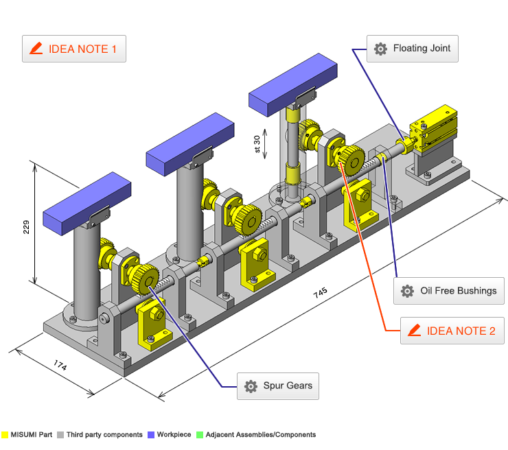
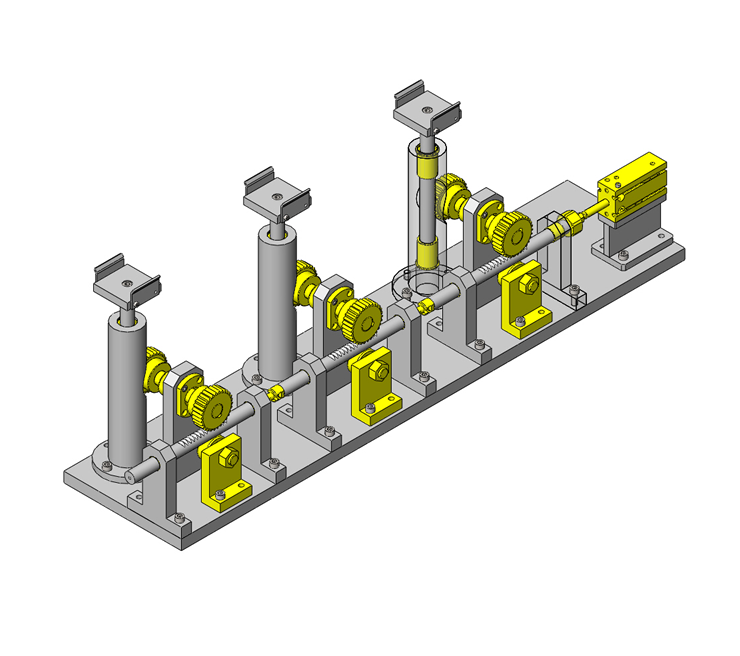
No.000153 Lifting Mechanism Using Rack and Pinions
32
Pneumatic lifting mechanism.
Relevant category


Floating Joint
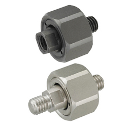
| Product name | Floating Connectors - Extra Short Threaded Stud Mount |
|---|---|
| Part number | FJCXS6-1.0 |
| Features | Effective when there is limited distance between cylinder and operated object |
Selection criteria
Effective when there is limited distance between the cylinder and the operated object.
Available sizes
■Floating Connectors - Extra Short Threaded Stud Mount
| Body/Cover | Joint | Spring | Washer | |||||
|---|---|---|---|---|---|---|---|---|
| Material | Surface Treatment | Material | Surface Treatment | Hardness | Material | Material | Surface Treatment | Hardness |
| 1045 Carbon Steel | Black Oxide | 1045 Carbon Steel | Black Oxide | 35〜45 HRC | 304 Stainless Steel−WPB | 304 Stainless Steel | Nitriding Treatment | 600HV〜 |
| 304 Stainless Steel | − | 420 Stainless Steel (440C Stainless Steel) | − | |||||
■Sizes
| Thread Dia. - Pitch | Tap Depth | Thread Length | Allowable Misalignment | Allowable Angular Misalignment | Body Thickness | Body Hex Size |
|---|---|---|---|---|---|---|
| M5-0.8 | 14.9 | 6 | 0.5 | 4° | 14 | 24 |
| M6-1.0 | ||||||
| M8-1.25 | 17.1 | 8.5 | 15.5 | 27 | ||
| M10-1.25 | 21.9 | 10 | 19.5 | 30 | ||
| M14-1.5 | 23.6 | 11 | 1 | 5° | 22 | 38 |

Oil Free Bushings
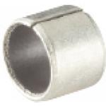
| Product name | Oil Free Bushings - Multi - Layer LF |
|---|---|
| Part number | MDZB15-15 |
| Features | Has a Thin wall and is compact. |
Selection criteria
Suitable for linear motion applications that do not require high accuracy.
Available sizes
■Oil Free Bushings - Multi - Layer LF
| Material |
|---|
| Ethylene Tetrafluoride Resin Layer with Filler Material Sintered Bronze Layer Steel-backed Metal Layer (SPCC: Tin Plating) |
■Sizes and Dimensions
| I.D.(mm) | Length(mm) |
|---|---|
| 3 | 3, (4), 5, (6) |
| 4 | (3), 4, (5), 6, (8) |
| 5 | (3), 4, 5, 6, (8) |
| 6 | (3), (4), 5, 6, 8, (10), (12) |
| 8 | (5), 6, 8, 10, 12, (15) |
| 10 | 6, 8, 10, 12, 15, (20) |
| 12 | 6, 8, 10, 12, 15, (20) |
| 13 | (8), 10, (12), 15, (20) |
| 15 | (8), 10, 12, 15, 20, (25) |
| 16 | 10, (12), 15, 20, (25) |
| 18 | 10, 12, 15, 20, (25), (30) |
| 20 | 10, 12, 15, 20, 25, (30) |
| 22 | 10, 12, 15, 20, (25), (30) |
| 25 | 10, 12, 15, 20, 25, (30), (35) |
| 30 | 12, 15, 20, 25, 30, (35), (40), (50) |
| 35 | 12*, 20, 25, 30, (35), 40, (50) |
| 40 | 12, (15), 20, 25, 30, (35), 40, (50) |
| 50 | 20, (25), 30, (35), 40, (50), (60) |
Length( ) is for Straight Type only
Length * is for Flanged Type only
Selection Steps
■Multi-Layer LF Bushings Selection Steps
- Determine Operating Conditions
- Specify the overall dimensions of the slide mechanism, then check required conditions for bushings such as the speed and load.
↓
- Specifying the Bearing Dimensions of Multi-Layer LF Bushings.
- Confirm the PV value and allowable maximum PV value, as well as the need of external lubrication.
↓
- Determining the Bearing Materials of Multi-Layer LF Bushings.
- Confirm the operating temperature and atmospheric temperature near the bearing.
↓
- Determining the Bearing Peripheral Section of Multi-Layer LF Bushings.
- Confirm the materials, roughness and rigidity of housing.
Accuracy Info
■Internal Dia. Tolerance of Multi-Layer LF Bushings
| I.D. (mm) | I.D. tolerance (mm) |
|---|---|
| 3 | -0.025 -0.024 |
| 4 | -0.025 -0.037 |
| 5 | |
| 6 | |
| 8 | -0.025 -0.040 |
| 10 | |
| 12 | -0.025 -0.043 |
| 13 | |
| 15 | |
| 16 | |
| 18 | |
| 20 | -0.025 -0.046 |
| 22 | |
| 25 | |
| 30 | |
| 35 | -0.025 -0.050 |
| 40 | |
| 50 |
Performance info.
■Allowable properties of Multi-Layer LF Bushing (Reference values)
| Non-lubricated | |
|---|---|
| Maximum Allowable Load | 49.0N/mm² |
| Maximum Allowable Velocity | 0.65m/s |
| Maximum Allowable PV Value | 3.60N/mm²・m/s |

Spur Gears
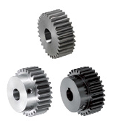
| Product name | Spur Gears - Pressure Angle 20Deg., Module 1.5 |
|---|---|
| Part number | GEAKB1.5-30-15-B-16N |
Selection criteria
Selected to efficiently convert horizontal motion into multiple vertical motions.
Available sizes
■Spur Gears - Pressure Angle 20Deg., Module 1.5
| Material | Surface Treatment | Accessory |
|---|---|---|
| 1045 Carbon Steel | ― | Set Screw (4137 Alloy Steel Black Oxide) |
| Black Oxide | ||
| Electroless Nickel Plating | ||
| 304 Stainless Steel | ― | Set Screw(304 Stainless Steel ) |
■Sizes and Dimensions
| Type | Module | Number of teeth | Shaft bore DIA. (1 mm Increment) | |
|---|---|---|---|---|
| Straight Bore Straight Bore + Tap | Keyway Keyway + Tap | |||
| Straight Bore Straight Bore + Tap Keyway Keyway+Tap | 1.5 | 12 | 6-12 | 8N |
| 13 | 6-13 | |||
| 14 | 6-8 | |||
| 16 | 6-12 | 8N-12N | ||
| 17 | ||||
| 18 | 6-13 | |||
| 19 | 6-15 | |||
| 20 | 6-16 | |||
| 21 | ||||
| 22 | 6-17 | |||
| 23 | 6-18 | 8N-13N | ||
| 24 | 6-20 | 8N-15N | ||
| 25 | ||||
| 26 | 6-22 | 8N-17N | ||
| 27 | 6-23 | 8N-18N | ||
| 28 | ||||
| 29 | 6-24 | 8N-19N | ||
| 30 | ||||
| 34 | 6-28 | 8N-24N | ||
| 35 | ||||
| 36 | ||||
| 38 | 6-31 | 8N-28N | ||
| 40 | 8-31 | 10N-28N | ||
| 42 | ||||
| 44 | ||||
| 45 | ||||
| 46 | ||||
| 48 | 8-35 | 10N-31N | ||
| 50 | ||||
| 52 | ||||
| 54 | 12-35 | 12N-31N | ||
| 55 | ||||
| 56 | ||||
| 58 | ||||
| 60 | 12-38 | 12N-35N | ||
| 62 | ||||
| 64 | ||||
| 65 | ||||
| 66 | ||||
| 68 | ||||
| 70 | 12-45 | 12N-42N | ||
| 72 | ||||
| 75 | ||||
| 84 | ||||
| 85 | ||||
| 90 | ||||
| 95 | ||||
| 100 | ||||
| 120 | 12-49 | 12N-45N | ||
| Gear specifications | Shaft Bore Specs. | |||
|---|---|---|---|---|
| Straight Bore | Straight Bore +Tap | Keyway | Keyway +Tap | |
| Diameter Shape | ○ | ○ | ○ | |
| No Hub | ○ | ○ | ||
| With Hub | ○ | ○ | ○ | |
Accuracy Info
■Accuracy of Spur Gear
Gear accuracy: Previous JIS B 1702 4 Class (New JIS B 1702-1 - 8 class equivalent)
Shaft Bore Dia. Tolerance: H7


IDEA NOTE Convert a horizontal force to a vertical force.


-

-
 Terms of use of CAD data and simplified drawing data
- These terms and conditions (hereinafter referred to as “the Terms") set forth the conditions for downloading CAD data and simplified drawing data posted on https://th.misumi-ec.com/ (hereinafter referred to as the "Website") operated by MISUMI (THAILAND) CO., LTD. (hereinafter referred to as "MISUMI"). By downloading CAD data and simplified drawing data posted on the Website (hereafter referred to as “Data”), customers are deemed to have agreed to these Terms.
- 1. Purpose of Use
-
MISUMI offers the following:
1)CAD data found on the Website (3D CAD data, 3D Intermediate data and 2D CAD data) for the purpose of informing customers of the characteristics of the products offered by MISUMI or a manufacturer affiliated with MISUMI for use in their designs.
2)Simplified drawing data (in PDF format) for the purpose of checking the specifications of products. - 2. Characteristics of Data
- There may be a discrepancy in certain characteristics of products (for example: tolerance, surface roughness, chamfer, etc.) between the Data and the actual product. Furthermore, for the purpose of reducing the file size of the Data, some information such as oil groove shapes, threads, or spring shapes, may be removed from the Data.
- 3. Disclaimer
- MISUMI carefully creates the Data but makes no warranty as to the accuracy of the Data. MISUMI may at any time, and with no prior notice to customers, revise or delete Data. MISUMI assumes no responsibility for any damage or loss resulting from any revision or deletion of the Data, or any errors in said data. Customers are solely responsible for all aspects of their own designs, including those made using MISUMI’s CAD data. MISUMI may provide customers with design example data on the Website, but the quality, accuracy, functionality, safety, reliability, etc., of such data are not guaranteed. MISUMI may, at any time, and in its sole discretion, request that the customer cease its use of or destroy the Data in its possession. MISUMI may request the customer provide MISUMI documentation of such destruction.
- 4.Prohibited Acts
-
Customers or users of the Data, are prohibited from the following acts regarding the Data, in whole or in part:
(1)Requesting quotations or placing orders for products with third parties other than those authorized by MISUMI or its affiliates;
(2)Receiving quotations or orders for products from third parties by providing the Data to a third party or using the Data in their own business;
(3)Displaying links to the Website related to the Data on their own websites, etc., without MISUMI's consent;
(4)Using or reproducing the Data beyond the scope of the above-stated Purpose of Use;
(5)Modifying, altering, tampering with, translating, or adapting the Data;
(6)Selling, transferring, lending, sublicensing, or providing the Data to third parties in any way without MISUMI’s consent;
(7)Altering the content, reverse engineering, decompiling, disassembling, or analyzing the Data;
(8)Publicly disclosing or exhibiting the Data without MISUMI's consent;
(9)Using the Data for the purpose of providing products and services identical or similar to those of MISUMI;
(10)Performing acts that interfere with the proper functioning of this Website, such as acquiring Data in bulk. - 5. Copyright
-
All title and copyright in and to any information contained in the Data are owned by MISUMI or the relevant manufacturer affiliated with MISUMI and are protected by applicable copyright laws and international treaties. By downloading Data, the customer acquires no ownership rights of any kind in the intellectual property contained within. Without prior approval from MISUMI, no part of the Data may be utilized (reproduced, modified, reverse-engineered, uploaded, presented, sent, distributed, licensed, sold, or published) for any purpose other than that mentioned above.
In the event Data is found to have been to be used for any purpose other than that mentioned above or against any applicable laws, MISUMI may pursue any legal remedy available to it, which may result in forbidding the offending user from using the Data or accessing the Website. - 6. Third-Party Data
- MISUMI offers some Data provided by third parties. Such Data may be subject to separate terms and conditions, in addition to these terms. MISUMI makes no guarantee or warranty regarding Data from third parties.
- 7. Export Control
- Customers shall comply with all applicable laws and regulations regarding the export of the Data.
- 8. Amendments to the Terms
- MISUMI may, at any time, and in its sole discretion, modify these terms and conditions; any such modification will be effective immediately.
- 9. Severability
- If any term or provision of these Terms is invalid, illegal, or unenforceable in any jurisdiction, such invalidity, illegality, or unenforceability shall not affect any other term or provision of these Terms or invalidate or render unenforceable such term or provision in any other jurisdiction.
- 10.Miscellaneous
- These Terms and any disputes arising in connection therewith shall be exclusively governed by and construed in accordance with the laws of Thailand, without regard to its conflicts of law principles. The authorized courts in Thailand shall have exclusive jurisdiction to adjudicate any dispute arising in connection with these Terms.
- Revised: 16th November, 2025
CAD Download (Unit Assembly)
CAD Download: File Format
CAD Data Limitations
-
Assembly data shows the assembly drawings in the concept design phase. The sole purpose of the data is to explain the structure and functionality of the assembly and is not considered nor to be used as a final design.
You will need to edit the Data so that it meets your specific design conditions. -
Unit assembly Data consists of some sub-assemblies.
It is configured so that each sub-assembly unit can be used as it is or edited. - The Data for fabricated parts is based on easy-to-edit dimensions and shapes in sketches and histories.
- The Data including the third-part components are made by the Company.
* The part in the frame is a sub-assembly unit.
-

- * Unit assembly Data consists of some sub-assemblies.
It is configured so that each sub-assembly unit can be used as it is or edited.
Application Overview
Purpose
- Purpose
- To raise and lower multiple lifters using one air cylinder.
- Operation
- Use several rack and gear sets to move the lifters.
Points for use
- Individual workpieces are raised and lowered at the same time.
Target workpiece
- Shape: Connector
- Size: W150 x D40 x H25mm
Weight: 0.3 (3×0.1)Kg
Design Specifications
Operating Conditions or Design Requirements
- Upstroke/Downstroke: 30mm
- External dimensions: W174 x D745 x H229mm
Required Performance
- Load: Workpiece + lifting plate + racks = 12.8N
Selection Criteria for Main Components
- Select a cylinder with a tube inner diameter of φ20mm to lift the load (12.8N)
Design Evaluation
Verification of main components
- Validate cylinder thrust based on the applied load.
- Cylinder selection.
- Cylinder thrust.
Conditions (values): Mass applied to a gear (W) = 1.3kg, gravitational acceleration (g) =9.8m/s², and friction coefficient of the rack and pinions (μ) = 1. - Load F₁=μWg=1×1.3×9.8=12.8N
- Where the operating pressure is 0.5Mpa, cylinder thrust F₂=132N
- Cylinder thrust.
Other Design Consideration
- Three sets of rack and pinions can be assembled using common parts.
When installing the gears, their positions should be adjusted to reduce backlash.
Explore Similar Application Examples

-

-

-

-

-

-

-

-

-

-

-

-

-

-

-

-

-

-

-

Relevant category
-

-

-

-

-

-

-

-

-

-

-

-

-

-

-

-

-

-

-

-

-

-

-

-

-

-

-

-

-

-

-

-

-

-

-

-

-

-

-

-

-

-

-

-

-

-

-

-

-

-

-

-

-

-

-

-

-

-

-

-

-

-

-

-

-

-

-

-

-

-

-

-

-

-

-

-

-

-

-

-

-

-

-

-

-

-

-

-

-

-

-

-

-

-

-

-

-

-

-

-

-

-

-

-


Payment Methods
- Credit Card
-
- Bank
-
- Prompt Pay
-


Social Media
MISUMI Contact
Copyright © MISUMI Corporation All Rights Reserved.