(!) Since support from Microsoft will end on January 14 2020, Windows 7 user might not be able to use MISUMI website effectively. Please consider to update your system as ‘MISUMI Website system requirement’.


- inCAD Library Home
- > No.000223 Stacking Mechanism Using Cylinder
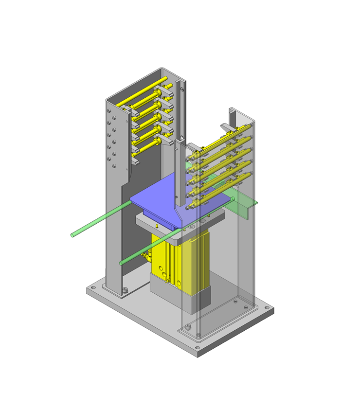
No.000223 Stacking Mechanism Using Cylinder
58
Vertical stacking by one cylinder
Relevant category


Oil Free Bushing
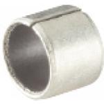
| Product name | Oil Free Bushings - Multi - Layer LF |
|---|---|
| Part number | MDZB8-10 |
| Features | Has a Thin wall and is compact. |
Selection criteria
Effective for oscillating motion part in a low speed by oil free.
Available sizes
■Oil Free Bushings - Multi - Layer LF
| Material |
|---|
| Ethylene Tetrafluoride Resin Layer with Filler Material Sintered Bronze Layer Steel-backed Metal Layer (SPCC: Tin Plating) |
■Sizes and Dimensions
| I.D.(mm) | Length(mm) | ||||||||||||||
|---|---|---|---|---|---|---|---|---|---|---|---|---|---|---|---|
| 3 | 4 | 5 | 6 | 8 | 10 | 12 | 15 | 20 | 25 | 30 | 35 | 40 | 50 | 60 | |
| 3 | ○ | ○ | ○ | ○ | - | - | - | - | - | - | - | - | - | - | - |
| 4 | ○ | ○ | ○ | ○ | ○ | - | - | - | - | - | - | - | - | - | - |
| 5 | ○ | ○ | ○ | ○ | ○ | - | - | - | - | - | - | - | - | - | - |
| 6 | ○ | ○ | ○ | ○ | ○ | ○ | ○ | - | - | - | - | - | - | - | - |
| 8 | - | - | ○ | ○ | ○ | ○ | ○ | ○ | - | - | - | - | - | - | - |
| 10 | - | - | - | ○ | ○ | ○ | ○ | ○ | ○ | - | - | - | - | - | - |
| 12 | - | - | - | ○ | ○ | ○ | ○ | ○ | ○ | - | - | - | - | - | - |
| 13 | - | - | - | - | ○ | ○ | ○ | ○ | ○ | - | - | - | - | - | - |
| 15 | - | - | - | - | ○ | ○ | ○ | ○ | ○ | ○ | - | - | - | - | - |
| 16 | - | - | - | - | - | ○ | ○ | ○ | ○ | ○ | - | - | - | - | - |
| 18 | - | - | - | - | - | ○ | ○ | ○ | ○ | ○ | ○ | - | - | - | - |
| 20 | - | - | - | - | - | ○ | ○ | ○ | ○ | ○ | ○ | - | - | - | - |
| 22 | - | - | - | - | - | ○ | ○ | ○ | ○ | ○ | ○ | - | - | - | - |
| 25 | - | - | - | - | - | ○ | ○ | ○ | ○ | ○ | ○ | ○ | - | - | - |
| 30 | - | - | - | - | - | - | ○ | ○ | ○ | ○ | ○ | ○ | ○ | ○ | - |
| 35 | - | - | - | - | - | - | - | - | ○ | ○ | ○ | ○ | ○ | ○ | - |
| 40 | - | - | - | - | - | - | ○ | ○ | ○ | ○ | ○ | ○ | ○ | ○ | - |
| 50 | - | - | - | - | - | - | - | - | ○ | ○ | ○ | ○ | ○ | ○ | ○ |
Accuracy Info
■Accuracy of Oil Free Bushing
| I.D. (mm) | I.D. tolerance (mm) |
|---|---|
| 3 | +0.047 +0.017 |
| 4 | |
| 5 | +0.055 +0.025 |
| 6 | |
| 8 | |
| 10 | +0.060 +0.030 |
| 12 | |
| 13 | |
| 15 | +0.060 +0.030 |
| 16 | +0.065 +0.035 |
| 18 | +0.070 +0.035 |
| 20 | +0.080 +0.045 |
| 22 | |
| 25 | +0.085 +0.050 |
| 30 | +0.090 +0.050 |
| 35 | +0.095 +0.055 |
| 40 | |
| 50 | +0.105 +0.065 |
Performance info.
■Allowable Properties of Oil free Bushing (Reference Values)
| Regular | Non-lubricated | |
|---|---|---|
| Maximum Allowable Load | 29N/mm² | |
| Maximum Allowable Velocity | 1.00m/s | 0.5m/s |
| Maximum Allowable PV Value | 3.25N/mm²・m/s | 1.65N/mm²・m/s |

Extra Thin Resin Washer

| Product name | Extra Thin Resin Washers -Abrasion Resistance- |
|---|---|
| Part number | SWSPS16-8-1.0 |
| Features | Extra thin washer with excellent low friction and abrasion resistance. |
Selection criteria
Effective for rotation force along thrust direction in low speed.
Available sizes
■Extra Thin Resin Washers -Abrasion Resistance-
Material: Polyslider.
■Sizes and Dimensions
| O.D. | Inner Dia. (Selectable) | Thickness | |||||||||
|---|---|---|---|---|---|---|---|---|---|---|---|
| 8 | 3 | 4 | 5 | - | - | - | - | - | - | - | 0.13 0.25 0.5 1.0 |
| 10 | - | 4 | 5 | 6 | - | - | - | - | - | - | |
| 12 | - | 4 | 5 | 6 | 8 | - | - | - | - | - | |
| 14 | - | - | 5 | 6 | 8 | 10 | - | - | - | - | |
| 15 | - | - | 5 | 6 | 8 | 10 | 12 | - | - | - | |
| 16 | - | - | - | 6 | 8 | 10 | 12 | - | - | - | |
| 20 | - | - | - | 6 | 8 | 10 | 12 | 15 | 16 | - | 0.25 0.5 |
| 25 | - | - | - | 6 | 8 | 10 | 12 | 15 | 16 | 20 | |
Accuracy Info
■Thickness Tolerance of Extra Thin Resin Washer (Abrasion Resistant Type)
| Thickness | 0.13 | 0.25 | 0.5 | 1.0 |
|---|---|---|---|---|
| Tolerance | ±0.013 | ±0.025 | ±0.05 | ±0.1 |
Performance info.
■Characteristic Data of Extra Thin Resin Washer (Abrasion Resistant Type)
| Item | Value |
|---|---|
| Tensile Strength (Mpa) | 98 |
| Elongation (%) | 60 |
| Friction Coefficient (μ) | 0.16~0.4 |
| Insulation Resistance (kV/mm) | 45 |

Shaft Collar
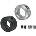
| Product name | Shaft Collars - Set Screw |
|---|---|
| Part number | PSCC8-8 |
| Features | Low Cost and Common Type. |
Selection criteria
Effective for positioning stopper along thrust direction of shaft accessories.
Available sizes
■Shaft Collars - Set Screw
| Material | Surface Treatment |
|---|---|
| 1045 Carbon Steel | Black Oxide |
| Electroless Nickel Plating | |
| 304 Stainless Steel | |
| 2017 Aluminum Alloy | - |
| Clear Anodize | |
| Black Anodize |
■Sizes and Dimensions
| I.D. (mm) | Thickness (mm) | |||||||||
|---|---|---|---|---|---|---|---|---|---|---|
| 6 | 8 | 10 | 12 | 15 | 16 | 18 | 20 | 22 | 25 | |
| 5 | ○ | ○ | - | - | - | - | - | - | - | - |
| 6 | ○ | ○ | ○ | - | - | - | - | - | - | - |
| 8 | - | ○ | ○ | - | - | - | - | - | - | - |
| 10 | - | ○ | ○ | - | - | - | - | - | - | - |
| 12 | - | ○ | ○ | ○ | - | - | - | - | - | - |
| 13 | - | ○ | ○ | - | - | - | - | - | - | - |
| 15 | - | ○ | ○ | ○ | - | - | - | - | - | - |
| 20 | - | - | ○ | ○ | ○ | - | - | - | - | - |
| 25 | - | - | - | ○ | ○ | - | ○ | - | - | - |
| 30 | - | - | - | - | - | ○ | - | ○ | - | - |
| 35 | - | - | - | - | - | - | - | ○ | - | - |
| 40 | - | - | - | - | - | - | - | ○ | ○ | - |
| 50 | - | - | - | - | - | - | - | - | - | ○ |
Accuracy Info
■Accuracy of Shaft Collars
| I.D. (mm) | I.D. Tolerance (H7) |
|---|---|
| 5 | +0.012 0 |
| 6 | |
| 8 | +0.015 0 |
| 10 | |
| 12 | +0.018 0 |
| 13 | |
| 15 | |
| 20 | +0.021 0 |
| 25 | |
| 30 | |
| 35 | +0.025 0 |
| 40 | |
| 50 |


-

-
 TERMS AND CONDITIONS FOR USE OF CAD DATA
-
Your access to the CAD data that MISUMI Corporation (hereinafter referred to as the Company) posts on this site (including 3D CAD data, intermediate 3D CAD data and 2D CAD data; hereinafter referred to as the Data) are of products manufactured and/or sold by the Company (hereinafter referred to as the Products) assumes that you have read and accepted these terms and conditions which govern your use of the Data. If you do not agree to these terms and conditions, you must stop using this website and the Data. You must not use the Data for any unlawful purpose or in any manner inconsistent with these terms and conditions.
- 1. CAD Data
- The Data is prepared for assisting the Company's users in the CAD design process by providing dimensions and other Product information. In order to provide the best speed and stability working within this site, the Product drawings were simplified to reduce the size of the Data. For instance, some of the Products are shown without the oil groove shape, screws or spring shape. Also, please be aware that the tolerance, surface roughness and/or chamfer of the Data may vary from the actual Products.
- 2. Disclaimer on Data
- While the Company has carefully prepared the Data, accuracy of the Data is not guaranteed and is subject to the variances as described above. The Company may also modify, add or delete the Data at any time without prior notice. The Company assumes no liability for any direct, indirect, consequential or special damages that you may claim resulted from your use of the Data or any changes to or deletions of the Data regardless of the reason. The Company provides no warranty as to the quality, accuracy, functionality, safety or reliability of the combination of Products and parts. Example applications and combinations of the Products are provided for illustrative purposes only.
- 3. Copyright
-
Copyrights to the content and the Data belong to the Company or the manufacturers of the Products. The said copyright is protected by the Copyright Act and international treaties. The use (including duplication, modification, uploading, posting, transmission, distribution, licensing, sales and publishing) of the Data except for the purpose to use the Data described above without prior approval of the Company is not allowed. The Data cannot be used for any purposes (including sales promotion) except for designing your machine. If you violate this provision or the laws or regulations, the Company may prohibit you from the use of the Data, the Company’s site and/or take legal action. So long as you comply with these terms and conditions, the Company grants to you a non-exclusive, non-transferable, revocable license to access and use the Data for the sole purpose of assisting you in designing machines that incorporate products.
In case that the CAD data is found to have been to be used for any purpose other than mentioned above or against the related laws, MISUMI may take legal actions, including the one for blocking the involved user from using CAD data and from accessing to the MISUMI site. - 4. Disclaimer of Warranty
- ANY AND ALL CONTENT APPEARING ON THIS WEB SITE IS PROVIDED FOR INFORMATIONAL PURPOSES ONLY. THIS WEB SITE, ITS CONTENT AND ITS LINKS ARE PROVIDED ON AN "AS IS" AND "AS AVAILABLE" BASIS AND ARE USED ONLY AT YOUR SOLE RISK, TO THE FULLEST EXTENT PERMISSIBLE BY LAW. THE COMPANY DISCLAIMS ALL WARRANTIES, EXPRESS OR IMPLIED, OF ANY KIND, REGARDING THIS WEB SITE (INCLUDING ITS CONTENT, HARDWARE, SOFTWARE AND LINKS), INCLUDING AS TO FITNESS FOR A PARTICULAR PURPOSE, MERCHANTABILITY, TITLE, NON INFRINGEMENT, RESULTS, ACCURACY, COMPLETENESS, ACCESSIBILITY, COMPATIBILITY, SECURITY AND FREEDOM FROM COMPUTER VIRUS. THE COMPANY WILL NOT BE LIABLE FOR ANY DAMAGES OR LOSSES, INCLUDING DIRECT, INDIRECT, CONSEQUENTIAL, SPECIAL, INCIDENTAL OR PUNITIVE DAMAGES AND/OR LOST PROFITS, IN CONNECTION WITH USE OF THE INTERNET, THIS WEB SITE, ITS CONTENT OR ITS LINKS
Further, the Company will not be liable to you for any failure or delay by the Company to provide access to the Data or any of its obligations under these terms and conditions where such failure or delay is the direct or indirect result of any circumstances beyond the Company's reasonable control (and the Company's obligations will be suspended for the duration of such circumstances).
CAD Download (Unit Assembly)
CAD Download: File Format
CAD Data Limitations
-
Assembly data shows the assembly drawings in the concept design phase. The sole purpose of the data is to explain the structure and functionality of the assembly and is not considered nor to be used as a final design.
You will need to edit the Data so that it meets your specific design conditions. -
Unit assembly Data consists of some sub-assemblies.
It is configured so that each sub-assembly unit can be used as it is or edited. - The Data for fabricated parts is based on easy-to-edit dimensions and shapes in sketches and histories.
- The Data including the third-part components are made by the Company.
* The part in the frame is a sub-assembly unit.
-
Your access to the CAD data that MISUMI Corporation (hereinafter referred to as the Company) posts on this site (including 3D CAD data, intermediate 3D CAD data and 2D CAD data; hereinafter referred to as the Data) are of products manufactured and/or sold by the Company (hereinafter referred to as the Products) assumes that you have read and accepted these terms and conditions which govern your use of the Data. If you do not agree to these terms and conditions, you must stop using this website and the Data. You must not use the Data for any unlawful purpose or in any manner inconsistent with these terms and conditions.
-

- * Unit assembly Data consists of some sub-assemblies.
It is configured so that each sub-assembly unit can be used as it is or edited.
Application Overview
Purpose
- Purpose.
- To receive workpieces and stack them vertically.
- Operation.
- The Following operations are repeated:
Workpiece feeding -> cylinder upstroke -> cylinder down stroke.
- The Following operations are repeated:
Target workpiece
- Shape: Pallet with brim
- Size: W150×D150×H30mm
- Weight: 0.6kg
Design Specifications
Operating Conditions or Design Requirements
- External dimensions: W320×D220×H481mm
- Upstroke: 100mm
Required Performance
- Difference between right and left ratchets: ±0.5mm
Selection Criteria for Main Components
- Arrange ratchets to receive workpieces properly.
- Select the cylinder stroke with consideration of the required receiving ratchet motion.
- Select the cylinder diameter in consideration of the workpiece weight and the quantity of workpieces.
Design Evaluation
Verification of main components
- Validate whether the selected cylinder is adequate for the workpiece load.
- (Selection of Air Cylinder).
- Conditions (values): Operation air pressure 0.5MPa, efficiency: 0.8
- Cylinder theoretical thrust: 402N
- Since the cylinder thrust is expressed by "theoretical thrust×efficiency",
the cylinder thrust is 402×0.8=321.6N
(Validation of Load Factor). - Conditions (values): Workpiece weight=0.6kg, workpiece quantity=5
- Since the load is expressed by "workpiece weight×workpiece quantity)×9.8",
the load is (0.6kg×5 pieces)×9.8=29.4N - Load factor (%) is expressed by "load/cylinder thrust)×100"
Thus, the load factor is (29.4/321.6)×100=9.1%<50%
-> The conditions are satisfied.
Other Design Consideration
- The lower most ratchets used for this mechanism can receive workpieces firmly. However, ratchets are provided at each stage to support each workpiece, because the lower most workpiece receives the weight of the workpieces stacked up thereon.
- The stroke and the arrangement are selected to secure space in which the ratchets can retrieve the workpieces.
- In this example, the quantity of stacked workpieces is set to five. If there is ample space to stack up workpieces, approximately 30 pieces can be stacked.
Explore Similar Application Examples

-

-

-

-

-

-

-

-

-

-

-

-

-

-

-

-

-

-

-

-

-

Relevant category
-

-

-

-

-

-

-

-

-

-

-

-

-

-

-

-

-

-

-

-

-

-

-

-

-

-

-

-

-

-

-

-

-

-

-

-

-

Relevant category
-

-

-

-

-

-

-

-

-

-

-

-

-

-

-

-

-

-

-

-

-

-

-

-

-

-

-

-

-

-

-

-

-

-

-

-

-

-

-

-

-

-

-

-

-

-

-

-

-

-

-

-

-

-


Payment Methods
- Credit Card
-
- Bank
-
- Prompt Pay
-


Social Media
MISUMI Contact
Copyright © MISUMI Corporation All Rights Reserved.