(!) Since support from Microsoft will end on January 14 2020, Windows 7 user might not be able to use MISUMI website effectively. Please consider to update your system as ‘MISUMI Website system requirement’.


- inCAD Library Home
- > No.000078 Soldering Fixture
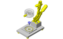
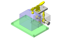
No.000078 Soldering Fixture
16
16
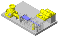
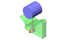
Workpiece holding using magnets.
Relevant category


Magnet
| Product name | Magnets - Cylindrical |
|---|---|
| Part number | HXN10-2 |
* Orange colored cells in the table below indicate the part numbers used in this example.
Selection criteria
Handy and economical as an item to hold a workpiece
Available sizes
■Magnets (Round)
| Material | Surface Treatment | Heat Resistant Temperature |
|---|---|---|
| High Force Neodymium Magnet | Nickel Plating | 60℃ |
| Neodymium Magnet | 80℃ | |
| Heat-resistant Neodymium Magnets | 150℃ | |
| Cobalt Magnet | 200℃ |
■Sizes and Dimensions
| O.D.(mm) | Length(mm) |
|---|---|
| 8 | 2 |
| 3 | |
| 5 | |
| 6 | |
| 8 | |
| 10 | |
| 10 | 2 |
| 3 | |
| 5 | |
| 8 | |
| 10 | |
| 12 | 2 |
| 3 | |
| 5 | |
| 8 | |
| 10 |
Performance info.
■Speeds / Loads (Load Info.) of Magnets
| I.D. (mm) | Length(mm) | Attraction Force (N) | Surface Magnetic Flux Density Gauss (G) | ||||
|---|---|---|---|---|---|---|---|
| High Force Neodymium | Neodymium Heat-resistant Neodymium | Cobalt | High Force Neodymium | Neodymium Heat-resistant Neodymium | Cobalt | ||
| 8 | 2 | - | 6.66 | 4.41 | - | 2400-2600 | 2000-2200 |
| 3 | 14.01 | 10.78 | 7.45 | 3500-3800 | 3200-3400 | 2700-2900 | |
| 5 | 23.31 | 17.93 | 11.96 | 4700-5000 | 4200-4400 | 3500-3700 | |
| 6 | 26.76 | 20.59 | - | 5100-5400 | 4700-4900 | - | |
| 8 | 29.94 | 23.03 | 15.39 | 5400-5700 | 4600-4800 | 3900-4100 | |
| 10 | 31.23 | 24.02 | - | 5600-5900 | 5000-5200 | - | |
| 10 | 2 | - | 7.84 | 5.29 | - | 2000-2200 | 1700-1900 |
| 3 | 18.34 | 14.11 | 9.41 | 3100-3400 | 2800-3000 | 2400-2600 | |
| 5 | 32.23 | 24.79 | 16.56 | 4300-4600 | 3800-4000 | 3200-3400 | |
| 8 | - | 34.3 | 23.03 | - | 4700-4900 | 4000-4200 | |
| 10 | 49.43 | 38.02 | 25.48 | 5500-5800 | 4900-5100 | 4100-4300 | |
| 12 | 2 | - | 9.02 | 5.98 | - | 1600-1800 | 1300-1500 |
| 3 | - | 16.46 | 11.07 | - | 2500-2700 | 2100-2300 | |
| 5 | - | 31.16 | 20.87 | - | 3600-3800 | 3000-3200 | |
| 8 | - | 46.55 | 31.07 | - | 4500-4700 | 3800-4000 | |
| 10 | - | 52.72 | 35.28 | - | 4800-5000 | 4000-4200 | |

Small Hex Posts

| Product name | Small Hex Posts- One End Threaded, One End Tapped |
|---|---|
| Part number | SLCB5.5-20 |
| Features | Suitable for Limited Spaces or Space-Saving required Places. |
* Orange colored cells in the table below indicate the part numbers used in this example.
Selection criteria
Handy as the feet of the reversed fixture or as the handle to open a lid.
Available sizes
■Small Hex Posts (Both Ends Tapped)
| Material | Surface Treatment |
|---|---|
| 1018 Carbon Steel or SUM43 | Black Oxide |
| Electroless Nickel Plating | |
| 303 Stainless Steel | - |
■Sizes and Dimensions
| Type | Opposite Side Size (mm) | Length(1mm Increments) |
|---|---|---|
| 1018 Carbon Steel or SUM43 Black Oxide | 5.5 | 5-12 |
| 13-20 | ||
| 1018 Carbon Steel or SUM43 Electroless Nickel Plating | 5.5 | 5-12 |
| 13-20 | ||
| 303 Stainless Steel | 4 | 5-10 |
| 15、20 | ||
| 5 | 5-10 | |
| 15、20 | ||
| 5.5 | 5-12 | |
| 13-20 |

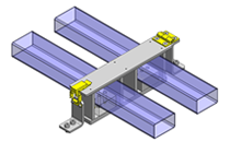
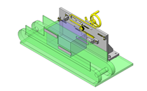
IDEA NOTE Best locating method for the cover with circular arc motion.
Cover is located with magnetic attraction and slotted holes/pins.


-
 Terms of use of CAD data and simplified drawing data
- These terms and conditions (hereinafter referred to as “the Terms") set forth the conditions for downloading CAD data and simplified drawing data posted on https://th.misumi-ec.com/ (hereinafter referred to as the "Website") operated by MISUMI (THAILAND) CO., LTD. (hereinafter referred to as "MISUMI"). By downloading CAD data and simplified drawing data posted on the Website (hereafter referred to as “Data”), customers are deemed to have agreed to these Terms.
- 1. Purpose of Use
-
MISUMI offers the following:
1)CAD data found on the Website (3D CAD data, 3D Intermediate data and 2D CAD data) for the purpose of informing customers of the characteristics of the products offered by MISUMI or a manufacturer affiliated with MISUMI for use in their designs.
2)Simplified drawing data (in PDF format) for the purpose of checking the specifications of products. - 2. Characteristics of Data
- There may be a discrepancy in certain characteristics of products (for example: tolerance, surface roughness, chamfer, etc.) between the Data and the actual product. Furthermore, for the purpose of reducing the file size of the Data, some information such as oil groove shapes, threads, or spring shapes, may be removed from the Data.
- 3. Disclaimer
- MISUMI carefully creates the Data but makes no warranty as to the accuracy of the Data. MISUMI may at any time, and with no prior notice to customers, revise or delete Data. MISUMI assumes no responsibility for any damage or loss resulting from any revision or deletion of the Data, or any errors in said data. Customers are solely responsible for all aspects of their own designs, including those made using MISUMI’s CAD data. MISUMI may provide customers with design example data on the Website, but the quality, accuracy, functionality, safety, reliability, etc., of such data are not guaranteed. MISUMI may, at any time, and in its sole discretion, request that the customer cease its use of or destroy the Data in its possession. MISUMI may request the customer provide MISUMI documentation of such destruction.
- 4.Prohibited Acts
-
Customers or users of the Data, are prohibited from the following acts regarding the Data, in whole or in part:
(1)Requesting quotations or placing orders for products with third parties other than those authorized by MISUMI or its affiliates;
(2)Receiving quotations or orders for products from third parties by providing the Data to a third party or using the Data in their own business;
(3)Displaying links to the Website related to the Data on their own websites, etc., without MISUMI's consent;
(4)Using or reproducing the Data beyond the scope of the above-stated Purpose of Use;
(5)Modifying, altering, tampering with, translating, or adapting the Data;
(6)Selling, transferring, lending, sublicensing, or providing the Data to third parties in any way without MISUMI’s consent;
(7)Altering the content, reverse engineering, decompiling, disassembling, or analyzing the Data;
(8)Publicly disclosing or exhibiting the Data without MISUMI's consent;
(9)Using the Data for the purpose of providing products and services identical or similar to those of MISUMI;
(10)Performing acts that interfere with the proper functioning of this Website, such as acquiring Data in bulk. - 5. Copyright
-
All title and copyright in and to any information contained in the Data are owned by MISUMI or the relevant manufacturer affiliated with MISUMI and are protected by applicable copyright laws and international treaties. By downloading Data, the customer acquires no ownership rights of any kind in the intellectual property contained within. Without prior approval from MISUMI, no part of the Data may be utilized (reproduced, modified, reverse-engineered, uploaded, presented, sent, distributed, licensed, sold, or published) for any purpose other than that mentioned above.
In the event Data is found to have been to be used for any purpose other than that mentioned above or against any applicable laws, MISUMI may pursue any legal remedy available to it, which may result in forbidding the offending user from using the Data or accessing the Website. - 6. Third-Party Data
- MISUMI offers some Data provided by third parties. Such Data may be subject to separate terms and conditions, in addition to these terms. MISUMI makes no guarantee or warranty regarding Data from third parties.
- 7. Export Control
- Customers shall comply with all applicable laws and regulations regarding the export of the Data.
- 8. Amendments to the Terms
- MISUMI may, at any time, and in its sole discretion, modify these terms and conditions; any such modification will be effective immediately.
- 9. Severability
- If any term or provision of these Terms is invalid, illegal, or unenforceable in any jurisdiction, such invalidity, illegality, or unenforceability shall not affect any other term or provision of these Terms or invalidate or render unenforceable such term or provision in any other jurisdiction.
- 10.Miscellaneous
- These Terms and any disputes arising in connection therewith shall be exclusively governed by and construed in accordance with the laws of Thailand, without regard to its conflicts of law principles. The authorized courts in Thailand shall have exclusive jurisdiction to adjudicate any dispute arising in connection with these Terms.
- Revised: 16th November, 2025
CAD Download (Unit Assembly)
CAD Download: File Format
CAD Data Limitations
-
Assembly data shows the assembly drawings in the concept design phase. The sole purpose of the data is to explain the structure and functionality of the assembly and is not considered nor to be used as a final design.
You will need to edit the Data so that it meets your specific design conditions. -
Unit assembly Data consists of some sub-assemblies.
It is configured so that each sub-assembly unit can be used as it is or edited. - The Data for fabricated parts is based on easy-to-edit dimensions and shapes in sketches and histories.
- The Data including the third-part components are made by the Company.
* The part in the frame is a sub-assembly unit.
-

- * Unit assembly Data consists of some sub-assemblies.
It is configured so that each sub-assembly unit can be used as it is or edited.
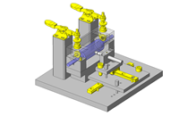
Application Overview
Purpose
- A fixture for soldering PC board.
Points for use
- Operating procedure
- The PC board is held down by the fixtures cover.
- User can perform soldering work on the first side of the PC board.
- After soldering the first side, lift up the cover, then remove and refit the PC board to its opposite side.
- Fold down the fixture cover again and begin soldering work on the 2nd side of the PC board.
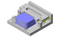
Target workpiece
- PC board
- Dims.: W70 x D45 x t1 (Also compatible with PCB W40 x D80 x t1)
Design Specifications
Operating Conditions or Design Requirements
- External dims.: W120 x D120 x H30
- Magnet; 7.84N
Required accuracy · Load
- Cover retaining force: 5.9N
Selection Criteria for Main Components
- Magnet
- Magnetic hold down force should be sufficient to keep the PCB in place during soldering, and yet minimal enough for easy lifting of the cover when soldering is complete.
- As an example, select magnets with attraction force of approximately 5.9N.
Design Evaluation
Verification of main components
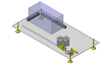
- Consider adding handle or hex posts for lifting of cover and overall handling of the fixture.
- When reversing, load applicable on the magnets: Cover + Hex posts + PCB = 45g + 10g + 5g = 60g = 0.59N
- Distance between the magnets and magnetic material: 2mm (Magnetic material: 4137 Alloy Steel, screw head)
- Assumed decay: 0.1
- Attraction to prevent cover opening: 0.59 / 0.1 = 5.9N
- Magnetic attraction can vary based on distance, temperature, material and size of magnetic body. Selection is to be made upon actual measurements.
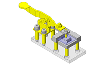
Other Design Consideration
- Since soldering is applied on reversed sides, hex posts are provided as feet on the cover side. The posts are also used as handles for cover open/close.
- Locating pins are used to locate the cover.
- Add notches as needed to avoid wire harness, etc.
- The hex socket screw heads are used as attracted member since the main body and the cover are made of non-magnetically permeable material.
Explore Similar Application Examples
Page
-
/
-

-
-

-

-
-

-

-

-

-

-

-
Relevant category
-

-

-

-

-

-

-

-

-

-

-

-
-

-

-

-
-

-

-
-

-

-

-

-

-

-

-
-

-

-

-

-

-

-

-

-

-

-

-

-

-

-

-

-

-

-

-

-
-

-
-

-

-

-

-

-

-

Payment Methods
- Credit Card
-
- Bank
-
- Prompt Pay
-


Social Media
MISUMI Contact
Copyright © MISUMI Corporation All Rights Reserved.