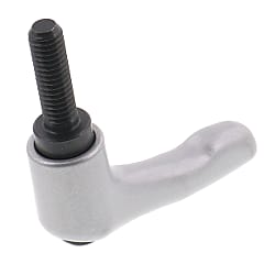
Clamp Lever (FKF, FKR)
Caution
Product Description
Machine lever for tightening and loosening screws without tools.
[Features]
・ In this type of lever handle, when the lever is pulled, the serrations engaged with each other are disengaged.
・ After tightening, you can turn the lever freely to any position.
・ Can be used in tight places where a lever cannot be turned 360°.
・ After screw tightening, the lever can be moved to an arbitrary position.
・ Main unit available in 4 colors (silver, black, red and orange).
[Applications]
・ For position-adjusting parts, such as slides and slotted holes, etc.
Clamp Lever Outline Drawing & Dimensions

FKF-BR tapped

FKF-OG tapped

FKR-SV stud

FKR-RE stud

Common parts outline drawing

Socket for both hexalobular and flathead screwdrivers

FKF tapped outline drawing

FKR stud outline drawing
| Size | R | M | H | D | H1 | H2 | D1 | S | A | a | W | No. of Teeth | Standard (Applicable Tool Size) | ||
|---|---|---|---|---|---|---|---|---|---|---|---|---|---|---|---|
| Flathead Screwdriver | Torx | ||||||||||||||
| FKF FKR | 5 | 40 | M5 × 0.8 | 31 | 14 | 24.5 | 34 | 10 | 4 | 7 | 5.5 | 1 | 16 | (-) 5.5 | T20 |
| 6 | M6 × 1 | ||||||||||||||
| 8 | 65 | M8 × 1.25 | 42.5 | 19 | 28.5 | 45.5 | 13.5 | 6.5 | 9.5 | 20 | |||||
| 10 | 80 | M10 × 1.5 | 54.5 | 22 | 37 | 58.5 | 16 | 10 | 11 | 22 | |||||
| 12 | 95 | M12 × 1.75 | 63 | 27.5 | 43 | 67.5 | 19 | 13 | 7.5 | 1.5 | 24 | (-) 7 | T27 | ||
| 16 | 110 | M16 × 2 | 73 | 32 | 49 | 77.5 | 23 | 12 | 15 | 26 | ((-) 6) | ||||
FKF Tapped
| Right Screw | Left Screw | Lf | Weight (g) |
|---|---|---|---|
| Part Number | Part Number | ||
| FKF5-** | - | 9 | 40 |
| FKF6-** | FKF6L-** | ||
| FKF8-** | FKF8L-** | 12 | 90 |
| FKF10-** | FKF10L-** | 14 | 130 |
| FKF12-** | - | 17 | 210 |
| FKF16-** | 23 | 330 |
FKR Stud
| Right Screw | Left Screw | L | Weight (g) |
|---|---|---|---|
| Part Number | Part Number | ||
| FKR5×10-** | - | 10 | 40 |
| FKR5×15-** | 15 | 41 | |
| FKR5×20-** | 20 | 42 | |
| FKR5×25-** | 25 | 43 | |
| FKR5×30-** | 30 | 45 | |
| FKR5×40-** | 40 | 47 | |
| FKR5×50-** | 50 | 49 | |
| FKR6×10-** | FKR6×10L-** | 10 | 40 |
| FKR6×15-** | FKR6×15L-** | 15 | 41 |
| FKR6×20-** | FKR6×20L-** | 20 | 42 |
| FKR6×25-** | FKR6×25L-** | 25 | 43 |
| FKR6×30-** | FKR6×30L-** | 30 | 45 |
| FKR6×40-** | - | 40 | 47 |
| FKR6×50-** | 50 | 49 | |
| FKR8×15-** | FKR8×15L-** | 15 | 100 |
| FKR8×20-** | FKR8×20L-** | 20 | 101 |
| FKR8×25-** | FKR8×25L-** | 25 | 102 |
| FKR8×30-** | FKR8×30L-** | 30 | 103 |
| FKR8×40-** | FKR8×40L-** | 40 | 110 |
| FKR8×50-** | - | 50 | 115 |
| FKR8×60-** | 60 | 120 |
| Right Screw | Left Screw | L | Weight (g) |
|---|---|---|---|
| Part Number | Part Number | ||
| FKR10×20-** | FKR10×20L-** | 20 | 150 |
| FKR10×25-** | FKR10×25L-** | 25 | 153 |
| FKR10×30-** | FKR10×30L-** | 30 | 157 |
| FKR10×40-** | FKR10×40L-** | 40 | 162 |
| FKR10×50-** | FKR10×50L-** | 50 | 170 |
| FKR10×60-** | - | 60 | 170 |
| FKR12×25-** | 25 | 235 | |
| FKR12×30-** | 30 | 240 | |
| FKR12×40-** | 40 | 246 | |
| FKR12×50-** | 50 | 252 | |
| FKR12×60-** | 60 | 260 | |
| FKR12×70-** | 70 *) | 270 | |
| FKR12×80-** | 80 *) | 280 | |
| FKR12×90-** | 90 *) | 290 | |
| FKR16×30-** | 30 | 380 | |
| FKR16×40-** | 40 | 390 | |
| FKR16×50-** | 50 | 405 | |
| FKR16×60-** | 60 | 420 | |
| FKR16×70-** | 70 *) | 430 | |
| FKR16×80-** | 80 *) | 440 | |
| FKR16×90-** | 90 *) | 450 |
Replace ** with color code for handle. Effective thread length is 60 mm.
Stud-Type Tightening Capacity
| Size | FKR | |||||
|---|---|---|---|---|---|---|
| 5 | 6 | 8 | 10 | 12 | 16 | |
| Thread Diameter | M5 | M6 | M8 | M10 | M12 | M16 |
| Turning Radius (mm) | 30 | 30 | 55 | 70 | 85 | 100 |
| Load Capacity (N) | 135 | 215 | 290 | 445 | 640 | 1,300 |
| Allowable Tightening Force (kN) | 3.1 | 4.3 | 8 | 12.8 | 18.6 | 33.5 |
Usage Example/Method

Lift the handle to disengage the teeth from the locking element.

Turn the lifted handle to the desired position.

When the hand is released, the lever is returned and clamped due to the force of the internal spring. (When the number of teeth is 20, the teeth engage with the locking element every 18° (360°/20 = 18°))