XYZ-Axis Manual Stages, Cross Roller Guide

Brand :
MISUMI
Caution
- Download Free! >>Economy Series Catalog ver2023 (TH-EN)_Part09 CLICK here
Product Description
- XYZ-Axis Manual Stages, Cross Roller Guide type, E-XYZPG series from MISUMI.
- This is an economy item, The price is cheaper than the MISUMI standard product.
- 3 stage sizes are available, 40, 60 and 80 mm.
- The load capacity can be selected from 9.8 N to 49 N.
- Minimum Reading is 10 μm.
- The material of XYZ-Axis Manual Stages E-XYZSG series are made of Aluminum Alloy with Black Anodized surface treatment.
- Can select 4 types of alteration for changing the position of the micrometer knob, Center (A), Side Up (C), Side Down (CU) and Reverse (R).
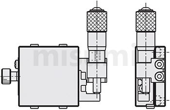
Dimensional Drawing of Manual XYZ-Axis Stages

*A40, A60, A80 are available sizes of the screw hole on sliding table
Specification Table of Manual XYZ-Axis Stages
■Specification Table of Manual XYZ-Axis Stages
■Alteration of Manual XYZ-Axis Stages
| Part Number | Positioning Stage Face (mm) | Movement (mm) | Load Capacity (N) | Straightness (μm) | Minimum Reading (μm) | Weight (kg) | |
| Type | No. | ||||||
| E-XYZPG | 40 | 40×40 | ±6.5 | 9.8 | Within 20 | 10 | 0.48 |
| 60 | 60×60 | 19.6 | 0.95 | ||||
| 80 | 80×80 | ±12.5 | 49 | 1.8 | |||
■Alteration of Manual XYZ-Axis Stages
| Alterations | Changing the position of the micrometer knob | |||
| Spec. | Center | Side Up | Side Down | Reverse |
| Code | A | C | CU | R |
Specification Overview of Manual XYZ-Axis Stages
■The movement amount of Manual XYZ-Axis Stages
drawing size is when the stroke is 0 mm, and the distance moved left and right based on this is the movement amount.
■Load capacity of Manual XYZ-Axis Stages
If it is used in excess of the rated load, the slide table may not move smoothly or may become stuck. Refer to the load capacity when installed horizontally and the "vertical" value when installed vertically,respectively.
Linear motion Please note that the accuracy may be lower than the values indicated in the product catalog if the slide table is installed vertically or upside down.
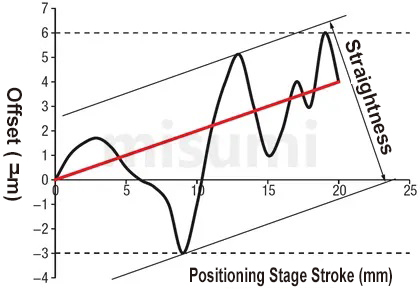
■Straightness This
refers to the maximum offset to the ideal movement axis (the straight line connecting the start and end points, the red line in the figure below. The black line is the actual motion trajectory) when driving the slidetable. Moves the full stroke.
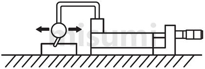
Detection method: Place a dial indicator on the slide table, place the pointer on the reference block, move the slide table the full stroke, and then measure the maximum displacement, i.e., straightness.


Product Features of Manual XYZ-Axis Stages
The price is low due to the simplified structure and improved processing technology.
How to use of Manual XYZ-Axis Stages
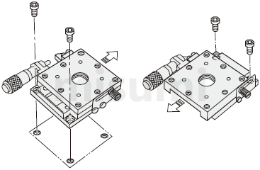
■How to install the X-axis sliding table
When installing the sliding table on the base, the method of moving the sliding table is basically adopted. See the image below.

■Installation direction of Manual XYZ-Axis Stages
 Choose from horizontal, inverted, side horizontal or vertical side installation. Caution is required for other installations.
Load resistance and accuracy vary greatly depending on the mounting posture.
○: Same level of load resistance.
△: Approximately 1/3 of the horizontal load resistance is a rough guideline, and the vertical load resistance listed in the product catalog is recommended.
■Using the X-axis slide table vertically
When using the X-axis slide table vertically, be careful with the travel direction not in the same direction as gravity.
When using the micrometer handle type slide, the slide is returned by the tension spring. If a force exceeding the spring load is applied, the slide table may fall.
Do not apply a load exceeding the vertical load range.
When installing the sliding table on the base, the method of moving the sliding table is basically adopted. See the image below.

■Installation direction of Manual XYZ-Axis Stages
| Description |  |  |  |  |
| Installation Direction | basic | Ceiling Mount | Side mount | Vertical mounting |
| Load resistance characteristics | ○ | ○ | △ | △ |
Choose from horizontal, inverted, side horizontal or vertical side installation. Caution is required for other installations. Load resistance and accuracy vary greatly depending on the mounting posture. ○: Same level of load resistance. △: Approximately 1/3 of the horizontal load resistance is a rough guideline, and the vertical load resistance listed in the product catalog is recommended. ■Using the X-axis slide table vertically
When using the X-axis slide table vertically, be careful with the travel direction not in the same direction as gravity.
When using the micrometer handle type slide, the slide is returned by the tension spring. If a force exceeding the spring load is applied, the slide table may fall.
| Incorrect usage | Correct usage |
 |  |
Do not apply a load exceeding the vertical load range. Caution of Manual XYZ-Axis Stages
■Stage usage environment of Manual XYZ-Axis Stages
Usage environment: 10~50℃, 20~70%RH (non-condensing)
Recommended usage environment: 22±5℃, 20~70%RH (non-condensing)
■Guide mechanism of Manual XYZ-Axis Stages
Since a cross roller guide is used as the guide mechanism, inject lubricant in a timely manner according to the usage conditions to prevent the life of the cross roller guide from being reduced and deteriorated due to lubricantreduction.
■Clamping mechanism of Manual XYZ-Axis Stages
①The clamping mechanism of the slide table is fixed by the frictional force generated by the fastening screw, so if the external force exceeds the frictional force of the clamping mechanism, the slide table will move. The user musttake appropriate measures during use to prevent the table surface from moving.
②Holding force refers to the value of the force that prevents the slide table from moving in the clamped state. The maximum holding force varies depending on the tightening torque, so ensure sufficient safety factors when designing.
■A slide table with a micrometer knob mounted on the transport mechanism is generally called a standard type if it has a shape like the figure below. You can freely select by combining the installation space, installation posture, andoperation method. However, there are some models where the installation position of the micrometer knob cannot be changed due to the product structure.
■There may be cases where the upper and lower tables are deformed due to differences in the flatness of the installation surface. Deformation of the table surface causes backlash, loosening due to failure to obtain the specifiedpreload, and poor sliding due to excessive preload. Therefore, it is recommended to maintain the flatness of the installation surface at approximately 5 microns.
Product Overview
MISUMI E-XYZPG series crossed roller guide type positioning stages are economy series positioning stages. It can be used as a positioning stage for simple position adjustment. The body is made of aluminum alloy to achieve light weight; the surface is black anodized. Crossed roller guide is used for guiding, which can meet the required operating accuracy. Prices have been significantly reduced due to local production in China and improved machining process.
Product Features
Feature 1: Production cycle is shortened, shipped within 5 days at the earliest
Feature 2: Low price is achieved by simplifying the structure and improving the machining process.
Feature 3: A wide range of alterations are available to enable installation and operation under different conditions.
Feature 4: By improving the clamping mechanism, the holding force of the positioning stage is greater than that of the standard type clamping mechanism.
■Amount of travel
The catalog drawing size is the state of travel 0mm, and taking this as reference, the distance moved in the left and right directions is the amount of travel.
■Load capacity
is the force in N that the positioning stage can withstand when the center of gravity of the workpiece is in the center of the positioning stage. If used in excess of the load capacity, the positioning stage may not move properly or get stuck. Refer to the values of "Horizontal" and "Vertical" for the load resistance for horizontal and vertical installation respectively. Note that when the linear motion positioning stage is installed vertically or upside down, the accuracy may be less than the value indicated in the catalog.
■Straightness
The maximum offset relative to the ideal axis of movement (the line connecting the start and end points is shown as the red line in the figure below. The black line is the actual trajectory of movement.) when the positioning stage moves at full stroke. Detection method: Place the micrometer on the positioning stage, with the pointer held against the reference block, let the positioning stage move at full stroke, and measure its maximum displacement, which is the straightness.
Feature 2: Low price is achieved by simplifying the structure and improving the machining process.
Feature 3: A wide range of alterations are available to enable installation and operation under different conditions.
Feature 4: By improving the clamping mechanism, the holding force of the positioning stage is greater than that of the standard type clamping mechanism.
Specifications Overview
| Type |  Material Material |  Surface Treatment Surface Treatment | Movement (mm) | Load Capacity (N) | Straightness |
| E-XYZPG | Aluminum Alloy | Black Anodized | ±6.5~±12.5 | 9.8~49 | Within 10μm |
■Amount of travel
The catalog drawing size is the state of travel 0mm, and taking this as reference, the distance moved in the left and right directions is the amount of travel.
■Load capacity
is the force in N that the positioning stage can withstand when the center of gravity of the workpiece is in the center of the positioning stage. If used in excess of the load capacity, the positioning stage may not move properly or get stuck. Refer to the values of "Horizontal" and "Vertical" for the load resistance for horizontal and vertical installation respectively. Note that when the linear motion positioning stage is installed vertically or upside down, the accuracy may be less than the value indicated in the catalog.
■Straightness
The maximum offset relative to the ideal axis of movement (the line connecting the start and end points is shown as the red line in the figure below. The black line is the actual trajectory of movement.) when the positioning stage moves at full stroke. Detection method: Place the micrometer on the positioning stage, with the pointer held against the reference block, let the positioning stage move at full stroke, and measure its maximum displacement, which is the straightness.


Usage Method
■Installation Method of X-Axis Positioning Stage
When mounting the positioning stage to the base, basically it is mounted by moving the positioning stage surface. Refer to the following diagram.
 The above diagram is for demonstration purpose only. Refer to each catalog or 3D data for detailed shapes and specifications of the positioning stage.
■Mounting Posture
Horizontal, inverted, side-mounted horizontal or side-mounted vertical installation options are available. Other installation methods should be given more attention.
Load capacity and accuracy will change greatly depending on the mounting posture.
○:Same as horizontal load capacity.
△:About 1/3 of the horizontal load capacity is the approximate standard, if the catalog contains the vertical load capacity, it should be given priority.
■Vertical Use of X-Axis Positioning Stage
When using the X-axis positioning stage vertically, pay attention to the feed direction, which should not be in the same direction as gravity.
When using a micrometer knob type positioning stage, note that the positioning stage is reset by extension spring. If the force applied is greater than the spring load, the positioning stage surface may fall. For such occasions, alterations can be used as a solution.
Avoid applying loads that exceed the load carrying range in the vertical direction.
When mounting the positioning stage to the base, basically it is mounted by moving the positioning stage surface. Refer to the following diagram.

 The above diagram is for demonstration purpose only. Refer to each catalog or 3D data for detailed shapes and specifications of the positioning stage.
■Mounting Posture
| Diagram |  |  |  |  |
| Mounting Posture | Horizontal | Inverted | Side-Mounted Horizontal | Side-Mounted Vertical |
| Load Resistance Characteristics | ○ | ○ | △ | △ |
Horizontal, inverted, side-mounted horizontal or side-mounted vertical installation options are available. Other installation methods should be given more attention.Load capacity and accuracy will change greatly depending on the mounting posture.○:Same as horizontal load capacity.△:About 1/3 of the horizontal load capacity is the approximate standard, if the catalog contains the vertical load capacity, it should be given priority.■Vertical Use of X-Axis Positioning Stage
When using the X-axis positioning stage vertically, pay attention to the feed direction, which should not be in the same direction as gravity.
When using a micrometer knob type positioning stage, note that the positioning stage is reset by extension spring. If the force applied is greater than the spring load, the positioning stage surface may fall. For such occasions, alterations can be used as a solution.
| Wrong Usage Method | Correct Usage Method |
| (Usually) If the force applied exceeds the tensile load of the spring, the positioning stage surface may slip off because it cannot support the weight. | After selecting the alteration of the micrometer knob position change, the positioning stage surface does not fall even when used vertically. |
 |  |
Avoid applying loads that exceed the load carrying range in the vertical direction.Example of Use
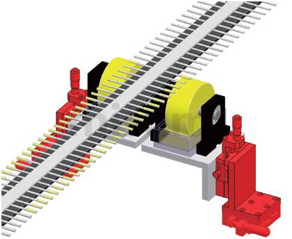
Mechanism name: Cotton swab glue application position adjustment

Example of Use
| Electronics/Home Appliance | Automotive | Medical | ||
 |  |  | ||
| Smart Phones | Semiconductor | Lithium battery | ||
 |  |  |
Precautions
■Operating temperature and environment
Recommended operating environment: 10~50℃, 20~70%RH (no condensation)
Accuracy assurance environment: 22±5℃, 20~70%RH (no condensation)
■Guiding mechanism
This positioning stage adopts crossed roller guide as the guiding mechanism. Please refill the lubricant at the right time according to the usage conditions to prevent the life of crossed roller guide from being shortened due to the decrease of lubricant and aging.
■Clamping mechanism
①The clamping mechanism of the positioning stage is fixed by the frictional force generated by the fastening screw, so when the applied external force exceeds the frictional force of the clamping mechanism section, it will cause the positioning stage to move. The user should take appropriate measures to avoid movement of the positioning stage surface during use. If clamping reinforcement is required, disc clamping or opposite clamping can be selected.
②The holding force is the value of the force that keeps the positioning stage surface from moving in the clamped condition. Since the maximum holding force varies with the tightening torque, please ensure a sufficiently large safety factor when designing.
■Feed mechanism
The shape of a positioning stage with a micrometer knob installed as shown in the figure below is generally called the standard type. Free selection is possible by combining the installation space, mounting posture, and operation method. However, due to the structure of the product, there are some models where the installation position of the micrometer knob cannot be changed. For details, refer to the [Alteration] at the bottom of each product page.
■Flatness of the mounting surface
The upper and lower positioning stage surface may be deformed due to the different flatness of its mounting surface. Deformation of the positioning stage surface may result in gaps, looseness due to failure to obtain the specified preload, or poor sliding due to excessive preload. Therefore, it is recommended that the flatness of the mounting surface be kept at about 5 microns.
Recommended operating environment: 10~50℃, 20~70%RH (no condensation)
Accuracy assurance environment: 22±5℃, 20~70%RH (no condensation)
■Guiding mechanism
This positioning stage adopts crossed roller guide as the guiding mechanism. Please refill the lubricant at the right time according to the usage conditions to prevent the life of crossed roller guide from being shortened due to the decrease of lubricant and aging.
■Clamping mechanism
①The clamping mechanism of the positioning stage is fixed by the frictional force generated by the fastening screw, so when the applied external force exceeds the frictional force of the clamping mechanism section, it will cause the positioning stage to move. The user should take appropriate measures to avoid movement of the positioning stage surface during use. If clamping reinforcement is required, disc clamping or opposite clamping can be selected.
②The holding force is the value of the force that keeps the positioning stage surface from moving in the clamped condition. Since the maximum holding force varies with the tightening torque, please ensure a sufficiently large safety factor when designing.
■Feed mechanism
The shape of a positioning stage with a micrometer knob installed as shown in the figure below is generally called the standard type. Free selection is possible by combining the installation space, mounting posture, and operation method. However, due to the structure of the product, there are some models where the installation position of the micrometer knob cannot be changed. For details, refer to the [Alteration] at the bottom of each product page.

■Flatness of the mounting surface
The upper and lower positioning stage surface may be deformed due to the different flatness of its mounting surface. Deformation of the positioning stage surface may result in gaps, looseness due to failure to obtain the specified preload, or poor sliding due to excessive preload. Therefore, it is recommended that the flatness of the mounting surface be kept at about 5 microns.
Related Products
| X-Axis Motorized Positioning Stages | XY-Axis Motorized Positioning Stages | Z-Axis Motorized Positioning Stages | ||
 |  |  | ||
| Typical Model: C-XMBS420-L-A-2 | Typical Model: C-XYMBS420-L-A-2 | Typical Model: C-ZMBS420-L-A-2 | ||
| Advantages: low price, fast delivery | Advantages: low price, fast delivery | Advantages: low price, fast delivery |