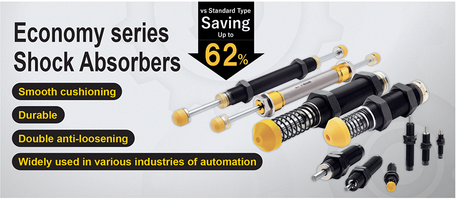
Shock Absorbers, Heavy Load Absorption Type

Caution
- Download Free! >>Economy Series Catalog ver2023 (TH-EN)_Part14 CLICK here
Product Description
- Shock Absorbers, Heavy Load Absorption Type from MISUMI
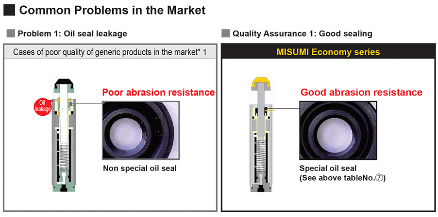
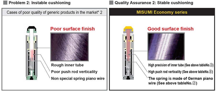
- Good abrasion resistance by utilizing special oil seal.
- Enhance cushioning stability due to good surface finishing.
- The spring is made of German piano wire.
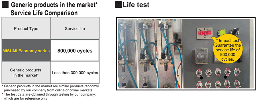
- Extend mechanical life, The service life of Shock Absorbers from MISUMI is up to 800,000 times.
- Max. Collision Velocity(m/s): 4.8 m/s
- Operating Environment Temperature: -5 to 70℃
- Significantly reduce noise and provide a quiet working environment.
- Improve the safety of mechanical running.
Economy Heavy Load Absorption Shock Absorber
- High Energy Absorption Capacity: Designed for heavy loads, it effectively absorbs high-energy impacts due to its unique internal pressure cylinder combination structure.
- Adjustable Energy Absorption: Optimize shock absorption by rotating the adjuster for tailored performance.
- Improved Production Efficiency: Smoothly stops impact objects, allowing for higher operating speeds and increased production output.
- Extended Mechanical Life: Reduces impact and vibration, protecting machinery and extending its lifespan.
- Noise Reduction: Significantly decreases noise levels, creating a quieter working environment.

MISUMI Standard

Cheaper Price

Product Variety

3D CAD Support
Product of Shock Absorbers Overview
The economy series heavy load Shock Absorbers has a unique internal pressure cylinder combination structure, capable of absorbing high energy impact load.
Optimal energy absorption effect is achievable by rotating the adjuster.
The advantages of using Shock Absorbers:
1. Improve production efficiency: equipment can be operated at high frequency and high speed to improve production efficiency because the shock absorber can stop the impact object smoothly.
2. Extend mechanical life: the buffer can absorb the energy generated by the impact, greatly reduce the impact and vibration caused by the object to the machine, and avoid damage due to impact vibration.
3. Improve Shock Absorbers product quality: the buffer eliminates the shock caused by impact objects and the damaging impact, allowing the smooth operation of the machine and equipment, and improving the product quality.
4. Significantly reduce noise, and provide a quiet working environment.
5. Improve the safety of mechanical running.
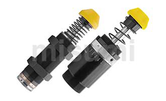
Product of Shock Absorbers Features
2. Miniaturized design and strong space adaptability.
3. Shock Absorbers energy smoothly and softly.
4. Shock Absorbers Abundant stock and fast delivery.
5. Long life with 800,000 times being used for reference.
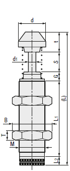
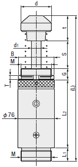
Dimensional Shock Absorbers Drawing
Specifications of Shock Absorbers Overview
| Impact Speed Type | Maximum Collision Velocity | Operating Environment Temperature | Reference number of replacements |
| Heavy Load Absorption Type | ~4.8m/s | -5 to 70℃ | 800,000 cycles |
■Shock Absorbers Material Table
 Shock Absorbers Material Shock Absorbers Material |  Shock Absorbers Surface Treatment Shock Absorbers Surface Treatment | |
| Body | Cover | |
| STKM11A | Urethane | Ferroferric Oxide Protective Film |
| Part Number |  Mating Accessories 1 |  Mating Accessories 2 | Mounting Screw Nominal (M) | Stroke (S) | Maximum Energy Absorbed (E') | Maximum Equivalent Mass(me') (kg) | Maximum Collision Velocity (M/S) | Total Length (L) | L1 | L2 | T | t | d | d1 | G | B (Both sides width) | ||
 Type Type |  No. No. | (J)Per Cycle (J) | Per minute (J) | |||||||||||||||
| E-MSZXAD | 4225 | No Symbol (Not Provided) SC (Provided) | No symbol (Not Provided) F (Provided) | M42×1.5 | 25 | 260 | 2160 | 3000 | 3.6 | 191 | 98.5 | 20 | 15 | 33.5 | 44.5 | 12 | 14 | 50 |
| 4250 | M42×1.5 | 50 | 500 | 2580 | 4000 | 4.8 | 258 | 135.5 | 20 | 15 | 38.5 | 44.5 | 12 | 14 | 50 | |||
| 4275 | M42×1.5 | 75 | 750 | 3110 | 6000 | 4.8 | 308 | 160.5 | 20 | 15 | 38.5 | 44.5 | 12 | 14 | 50 | |||
| 64050 | None | UNF 2 1/2-12 | 50 | 1200 | 2600 | 12727 | 3.5 | 247 | 26 | 97 | 10 | 51 | 59 | 20 | 23 | 76 | ||
| 64100 | UNF 2 1/2-12 | 100 | 2400 | 3200 | 18181 | 3.5 | 347 | 26 | 147 | 10 | 51 | 59 | 20 | 23 | 76 | |||
| 64150 | UNF 2 1/2-12 | 150 | 3600 | 4200 | 23636 | 3.5 | 467 | 26 | 207 | 10 | 61 | 59 | 20 | 23 | 76 | |||
Example of Shock Absorbers Use
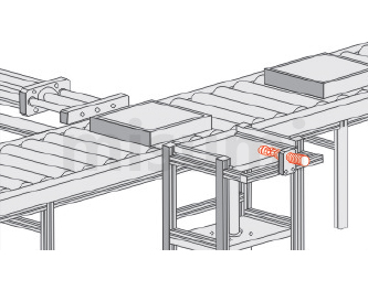
Example of Shock Absorbers Use 1
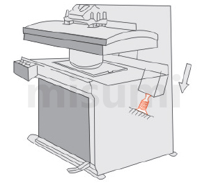
Example of Shock Absorbers Use 2
Precautions Shock Absorbers
| Coarse Outer Diameter (mm) | M8×1.0 | M10×1.0 | M12×1.0 | M14×1.5 | M20×1.5 | M25×1.5 | M27×1.5 |
| Tightening torque of nut (N.m) | 3.9 | 7.8 | 7.8 | 9.8 | 29.4 | 49 | 58.8 |
2. Pay attention to check whether the head circlip is off.
■ Overloaded buffer will cause abnormal increase in the internal pressure of the buffer tube, making the head circlip off, and internal parts may pop up and cause injury.
■ When the buffer with the head circlip is working, please keep your face and other parts away from it.
3. Please pay attention to the splash of the broken buffer head due to impact.
■ Shock Absorbers Overload use will cause damage to the head, resulting in injury.
■ It is recommended to install an anti-splashing cover.
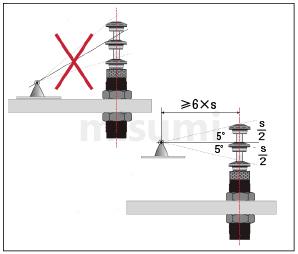
4. Please pay attention to lateral misalignment load and lateral misalignment angle.
■ When the lateral misalignment load exceeds ±2.5 degrees, it will cause piston rod bending, bad reset, and internal lateral misalignment friction, resulting in performance degradation and even product breakage.
Please aim at the center line of the buffer piston rod for impact. (If the lateral misalignment angle is greater than ±2.5 degrees, please use the angular misalignment Shock Absorbers (the range of lateral misalignment:± within 10 degrees)
5. Operating Temperature Range
■ Please use the buffer within the specified temperature range.
▪ Use outside the specified range will reduce the life of the seal packing and the pressure accumulating sponge, and cause the buffer to break.
6. Operating Environment Requirements
■ Please do not use it under medium or high pressure in a vacuum environment.
■ Keep the guide shaft clean, and avoid cutting powder, cutting fluid, water, etc. from being attached to the guide shaft, otherwise it will cause seal damage, oil leakage, poor buffer action, and buffer damage.
※ If you need to use it in the cutting fluid environment, please Shock Absorbers choose Misumi’s cutting fluid resistant buffer series products. See Misumi's official website.
8. Shock Absorbers To prevent the buffer from increasing lateral load, the distance between the installation position of the buffer and the fulcrum should be equal to or greater than 6 times of the buffer stroke.
And when the side load and the buffer center line form an angle of 5°, the Shock Absorbers energy is the maximum.