Disc Couplings High Flexible, Double Disc

Caution
- Download Free! >> Misumi Economy_Series(THA)_Index04_Stepper_Motor_Coupling CLICK here
Product Description
· GCPSW Model Disc Couplings High Flexible, Double Disc.
· Body material: Aluminum alloy with Alumite Treatment surface.
· Spacer disc material is Stainless steel with
· Fastening Bolt, Set Screw: Steel SCM435.
· Fastening surface treatment with Ferro ferric Oxide Protective Film.
· Shaft Fastening Method: Lock bolt clamp and screw type.
· GCPSW Model Body size: 20 to 39.
· Allowable Angular misalignment 2 degree.
· Maximum Rotational Speed: 10,000 (r/min).
· Maximum Rotational Speed Range: 4001 ~ 10000 (r/min).
· Application : For Servo Motors / Stepping Motor.
Economy High Flexible Double Disc Coupling
- Exceptional flexibility for compensating axial, radial, and angular misalignments
- High transmission efficiency up to specified percentage.
- Suitable for high-speed applications with a maximum rotational speed up to specified RPM
- Lightweight and compact design allows for easy installation
- Ideal for medium to high power transmission

MISUMI Standard

Cheaper Price

Product Variety

3D CAD Support
Coupling Product Overview
The disc Coupling relies on the elastic deformation of the disc to compensate for the relative displacement of the connected two shafts, which is a high-performance flexible Coupling with strong metal components.
It is characterized by compact structure, no backlash, high strength, long service life, no rotation clearance, no influence of temperature and oil pollution, acid resistance, alkali resistance and corrosion resistance.
Applicable motor types: recommended for servo motors, stepping motors and general motors.
Coupling Product Feature
1. Strong ability to compensate for misalignment between two axes. Compared with tooth Coupling, angular displacement can be doubled. In case of radial displacement, reaction force is small, flexibility is large, and certain axial, radial and angular displacements are allowed.
2. It has obvious shock absorption, no noise and no wear.
3. Suitable for working in high temperature (-80+300) and harsh environment, and operate safely under shock and vibration conditions.
4. High transmission efficiency, up to 99.86%. Especially suitable for medium, high speed and high power transmission.
5. Simple structure, light weight, small in size and convenient assembly and disassembly. It can be assembled and disassembled without moving the machine (models with intermediate shaft), and requiring no lubrication.
6. It can accurately transmit the rotational speed without slip, and can be used for transmission of precision machinery
Dimensional Coupling Drawing
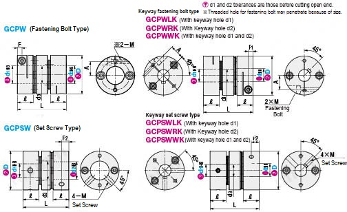
| TYPE |  Material Material |  Surface Treatment Surface Treatment |  Accessories Accessories | ||||||
| Standard Hole | d1 (One side) | d2 (One side) | d1, d2 (Both sides) | Body | Disc | Fastening Bolt, Set Screw | Body | Fastening Bolt, Set Screw | |
| GCPW | GCPWLK | GCPWRK | GCPWWK | Aluminum | Stainless Steel | SCM435 | Alumite Treatment | Ferroferric Oxide Protective Film | Fastening Bolt |
| GCPSW | GCPSWLK | GCPSWRK | GCPSWWK | Set Screw | |||||
Coupling Specifications Overview
Please order after selecting part number and parameters according to the selection steps
 to
to  . Please specify the shaft bore dia. within the range of d1≤d2.
Part Number (Type· D) D) | - |  d1 d1 | - | d2 |
| GCPW29 | - | 10 | - | 14 |
| Part Number | d1, d2 selection (But d1≤d2) | d3 | L | R | F1 | F2 | A | Fastening Bolt | Set Screw | |||||||||||||||
| Type | D | M | Tightening Torque | M | Tightening Torque | |||||||||||||||||||
| (N·m) | (N·m) | |||||||||||||||||||||||
| Clamping type GCPW GCPWLK GCPWRK GCPWWK | Set Screw type GCPSW GCPSWLK GCPSWRK GCPSWWK | 20 | *4 | *5 | 6 | 6.35 | 8 | 8.5 | 28.8 | 11 | 3.5 | 5.5 | 6.4 | M2.5 | 1.0 | M3 | 0.7 | |||||||
| 26 | *5 | 6 | 6.35 | 8 | 10 | 11 | 11.5 | 34.1 | 11.9 | 3.5 | 5.5 | 9 | ||||||||||||
| 29 | *5 | 6 | 6.35 | 8 | 10 | 11 | 12 | 14 | 14.5 | 34.3 | 11.9 | 3.5 | 5.5 | 10.5 | M4 | 1.7 | ||||||||
| 33 | 6 | 8 | 10 | 11 | 12 | 14 | 15 | 16 | 16.5 | 40 | 13 | 4 | 6.5 | 12 | M3 | 1.5 | ||||||||
| 39 | 8 | 10 | 11 | 12 | 14 | 15 | 16 | 18 | 19 | 49.4 | 16 | 4.75 | 8 | 14 | M4 | 3.5 | M5 | 4.0 | ||||||
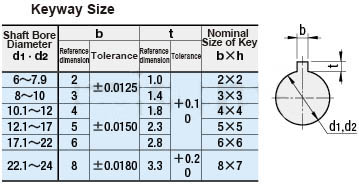
 d1 and d2*marked products without keyway hole.
■Characteristic Value
| Part Number | Allowable torque (N·m) | Allowable angle (°) | Allowable lateral misalignment (mm) | Static torsional rigidity (N·m/rad) | Maximum speed (r/min) | Moment of inertia (kg·m2) | Allowable axial amplitude (mm) | Compensation coefficient | Weight (g) | |||
| Type | D | GCPW | GCPSW | |||||||||
| GCPW GCPWLK GCPWRK GCPWWK | GCPSW GCPSWLK GCPSWRK GCPSWWK | 20 | 1 | 2 | 0.1 | 550 | 10000 | 1.1×10⁻⁶ | ±0.20 | 2 | 19 | 19 |
| 26 | 2 | 0.15 | 700 | 3.3×10⁻⁶ | ±0.20 | 31 | 33 | |||||
| 29 | 3 | 0.15 | 1200 | 5.5×10⁻⁶ | ±0.30 | 43 | 44 | |||||
| 33 | 5 | 0.2 | 1500 | 1.1×10⁻⁵ | ±0.40 | 60 | 65 | |||||
| 39 | 8 | 0.25 | 3350 | 2.7×10⁻⁵ | ±0.50 | 113 | 118 | |||||
Static torsional stiffness, moment of inertia and weight are the values at the maximum shaft dia..■Shaft slip torque (N·m)
When the shaft slip torque is less than the allowable torque, please use it below the shaft slip torque.| Part Number | d1, d2 | |||||||||||||
| Type | D | 4 | 5 | 6 | 6.35 | 8 | 10 | 11 | 12 | 14 | 15 | 16 | 18 | |
| GCPW GCPWLK GCPWRK GCPWWK | GCPSW GCPSWLK GCPSWRK GCPSWWK | 20 | 1.0 | 1.0 | 1.0 | 1.0 | 1.0 | - | - | - | - | - | - | - |
| 26 | - | 1.0 | 1.5 | 2.0 | 2.0 | 2.0 | 2.0 | - | - | - | - | - | ||
| 29 | - | 1.0 | 1.5 | 2.0 | 2.5 | 2.5 | 3.0 | 3.0 | 3.0 | - | - | - | ||
| 33 | - | - | 2.5 | - | 2.5 | 3.5 | 3.5 | 4.0 | 5.0 | 5.0 | 5.0 | - | ||
| 39 | - | - | - | - | 5.5 | 8.0 | 8.0 | 8.0 | 8.0 | 8.0 | 8.0 | 8.0 | ||
Coupling Precautions
1. The Coupling allows axis deviation, and transmits rotation angle and torque, but when the axis deviation exceeds the allowable value, vibration will occur or the service life will be drastically reduced.
Be sure to make calibration and adjustment.
2. Axis deviation includes lateral misalignment (parallel error of two axes), angular misalignment (angular error of two axes) and axial amplitude (axial movement of shaft).
Please calibrate and adjust the shaft to ensure that the axis deviation is below the allowable value recorded in the dimension and performance table of each product.
3. The allowable value of axis deviation recorded in the dimension and performance table refers to the situation when either lateral misalignment, angular misalignment or axial amplitude occurs alone. When more than two axis deviations occur at the same time, the corresponding allowable values are halved respectively.
4. Axis deviation not only occurs when assembling to the device, but also is caused by vibration, thermal expansion and bearing wear in operation. Therefore, it is recommended to set the axis deviation below 1/3 of the allowable value.
Example of Use Coupling
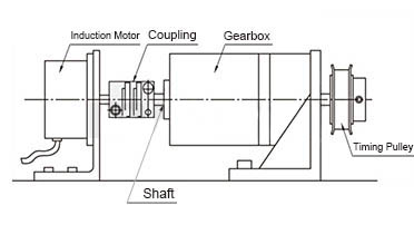
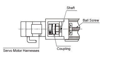
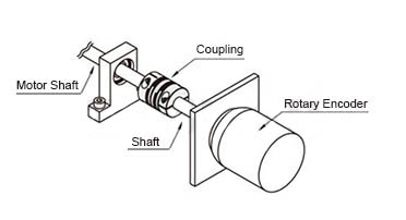
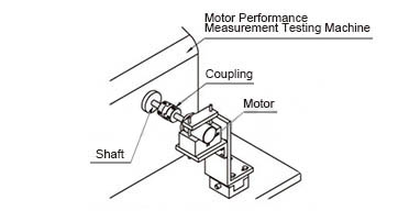
Coupling Usage Method
STEP1 Insert the Coupling
Confirm that the clamping bolt has been unscrewed, and then remove the dust, foreign matter and oil from the shaft and Coupling bore.
Then, when inserting the Coupling into the shaft, please be careful not to put the disc under excessive stress such as compression or tension.
STEP2 Use fixture to adjust
Please use fixture to adjust and fix the concentricity of the left and right hubs of the Coupling with high accuracy.
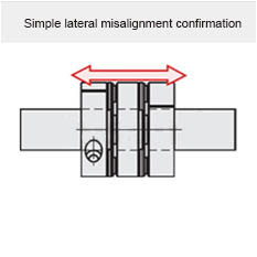
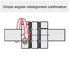
STEP3 Simple lateral misalignment and angular misalignment confirmation
Under the condition of unscrewed bolts, make the Coupling slide axially and confirm its smooth movement.
Then, rotate the Coupling to make sure it moves smoothly.
Lateral misalignment is not allowed for single disc type Coupling, so carry out positioning securely.
STEP4 Installation
Please adjust the shaft insertion amount according to the dimension ℓ in the product catalog, and use a torque wrench to tighten with the specified torque.
* If the specified torque cannot be reached once, please cross fasten the left and right clamps twice or three times.