Slit Couplings Long, Set Screw Type
Brand :
MISUMI
Caution
- Download Free! >> Misumi Economy_Series(THA)_Index04_Stepper_Motor_Coupling CLICK here
Product Description
This is an economy item, The price is cheaper than the MISUMI standard product.
[Features/Characteristics]
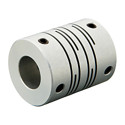
The metal elastic coupling is integrally formed with zero rotary clearance. Elastic action compensates radial, angular and axial deviations. Clockwise and counterclockwise rotary characteristics are identical.
Economy Long Slit Coupling - Set Screw Type
High rigidity Angular deviation Easy installation
- Superior aluminum alloy construction provides high durability
- Integrally formed metal elastic coupling with zero rotary clearance
- Compensates for radial, angular, and axial deviations, ensuring smooth operation
- Clockwise and counterclockwise rotary characteristics are identical
- Set screw fixing type allows for secure and easy installation

MISUMI Standard

Cheaper Price

Product Variety

3D CAD Support
Coupling Product Overview
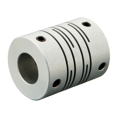
The parallel line coupling takes into account the shortening of slots without weakening the ability to bear and correct deviation. Short slots can enhance and overlap the torque rigidity of the coupling, so that it can bear considerable torque.
The parallel line coupling usually has 3 to 5 slots to deal with the problem of low torque rigidity.
The parallel line coupling takes into account the shortening of slots without weakening the ability to bear and correct deviation. Short slots can enhance and overlap the torque rigidity of the coupling, so that it can bear considerable torque.
Coupling Product Feature
【Features/Characteristics】The metal elastic coupling is integrally formed with zero rotary clearance. Elastic action compensates radial, angular and axial deviations. Clockwise and counterclockwise rotary characteristics are identical. Positioning screw fixing. Aluminum alloy material
【Usage】Suitable for standard motors
【Precautions】Moment of inertia and weight are calculated at the maximum shaft dia.
【Type】Grooved type
【Body Material】Aluminum alloy
【Fixing System】Set Screw fixing type
【Applicable Motors】Servo motors and stepping motors
■ Parallel line couplings are suitable for light load applications.
Dimensional Coupling Drawing
| TYPE | [M]Material | [ S ] Surface Treatment | [ A ] Accessories |
| GSASL | Aluminum | Alumite Treatment | Set Screw |
Coupling Specification Table
Please order after selecting part number and parameters according to the selection steps to . 


Part Number (Type·  D) D) | - |  d1 d1 | - | d2 |
| GSASL20 | - | 6 | - | 8 |
| Part Number | d1 | d2 | L | ℓ | Set Screw | F | ||||||||||||||
| Type | D | M (Coarse Thread) | Tightening torque (N·m) | |||||||||||||||||
| Set Screw GSASL | 8 | 2 | 2 | 3 | 14 | 3.5 | M3 | 0.3 | 1.7 | |||||||||||
| 3 | 3 | |||||||||||||||||||
| 12 | 3 | 3 | 4 | 5 | 18.5 | 2.5 | M2.5 | 0.5 | 5 | |||||||||||
| 4 | 4 | 5 | ||||||||||||||||||
| 5 | 5 | 6 | ||||||||||||||||||
| 16 | 4 | 4 | 5 | 6 | 23 | 6.4 | M3 | 0.7 | 3 | |||||||||||
| 5 | 5 | 6 | 8 | |||||||||||||||||
| 6 | 6 | 8 | ||||||||||||||||||
| 20 | 5 | 5 | 6 | 8 | 26 | 7 | ||||||||||||||
| 6 | 6 | 6.35 | 8 | 10 | ||||||||||||||||
| 6.35 | 8 | |||||||||||||||||||
| 8 | 8 | 10 | ||||||||||||||||||
| 10 | 10 | |||||||||||||||||||
| 25 | 6 | 6 | 8 | 10 | 31 | 8 | M4 | 1.7 | 4 | |||||||||||
| 6.35 | 8 | 10 | ||||||||||||||||||
| 8 | 8 | 10 | 12 | |||||||||||||||||
| 9.525 | 10 | |||||||||||||||||||
| 10 | 10 | 12 | ||||||||||||||||||
| 32 | 41 | 11 | 6 | |||||||||||||||||
| 8 | 8 | 12 | ||||||||||||||||||
| 10 | 10 | 11 | 12 | 14 | ||||||||||||||||
| 12 | 12 | 14 | ||||||||||||||||||
■Characteristic Value
| Part Number | Allowable torque (N·m) | Maximum rotational speed (rpm) | Moment of inertia (kg·m2) | Static torsional stiffness (N·m/rad) | Allowable lateral misalignment (mm) | Allowable Angular Misalignment ( ° ) | Allowable axial amplitude (mm) | Weight (g) | |
| Type | D | ||||||||
| GSASL | 8 | 0.1 | 10,000 | 1.2×10⁻⁸ | 25 | 0.1 | 2 | ±0.2 | 4.5 |
| 12 | 0.4 | 8.3×10⁻⁸ | 45 | ±0.3 | 6 | ||||
| 16 | 0.5 | 6.5×10⁻⁷ | 44 | ±0.4 | 9 | ||||
| 20 | 1 | 1.5×10⁻⁶ | 110 | 16 | |||||
| 25 | 2 | 4.2×10⁻⁶ | 215 | 0.15 | ±0.5 | 27 | |||
| 32 | 4 | 1.6×10⁻⁵ | 420 | 64 | |||||
| 40 | 8 | 3.2×10⁻⁵ | 700 | 0.2 | 134 | ||||
Coupling Precautions
■ Calibration and adjustment
1. The coupling allows axis deviation, and transmits rotation angle and torque, but when the axis deviation exceeds the allowable value, vibration will occur or the service life will be drastically reduced.
Be sure to make calibration and adjustment.
2. Axis deviation includes lateral misalignment (parallel error of two axes), angular misalignment (angular error of two axes) and axial amplitude (axial movement of shaft).
Please calibrate and adjust the shaft to ensure that the axis deviation is below the allowable value recorded in the dimension and performance table of each product.
3. The allowable value of axis deviation recorded in the dimension and performance table refers to the situation when either lateral misalignment, angular misalignment or axial amplitude occurs alone. When more than two axis deviations occur at the same time, the corresponding allowable values are halved respectively.
4. Axis deviation not only occurs when assembling to the device, but also is caused by vibration, thermal expansion and bearing wear in operation. Therefore, it is recommended to set the axis deviation below 1/3 of the allowable value.
Example of Use coupling
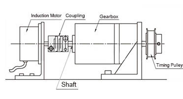

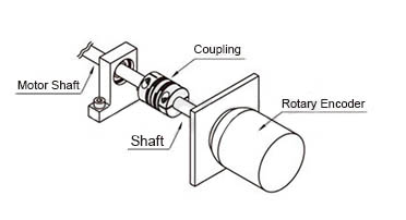
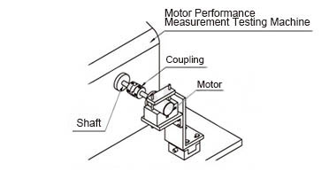
Coupling Usage Method
■Mounting method
STEP1 Insert the coupling
Confirm that the clamping bolt has been unscrewed, and then remove the dust, foreign matter and oil from the shaft and coupling bore.
Then, when inserting the coupling into the shaft, please be careful not to put the disc under excessive stress such as compression or tension.
STEP2 Use fixture to adjust
Please use fixture to adjust and fix the concentricity of the left and right hubs of the coupling with high accuracy.
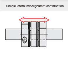
STEP3 Simple lateral misalignment and angular misalignment confirmation
Under the condition of unscrewed bolts, make the coupling slide axially and confirm its smooth movement.
Then, rotate the coupling to make sure it moves smoothly.
Lateral misalignment is not allowed for single disc type coupling, so carry out positioning securely.

STEP4 Installation
Please adjust the shaft insertion amount according to the dimension ℓ in the product catalog, and use a torque wrench to tighten with the specified torque.
* If the specified torque cannot be reached once, please cross fasten the left and right clamps twice or three times.
STEP1 Insert the coupling
Confirm that the clamping bolt has been unscrewed, and then remove the dust, foreign matter and oil from the shaft and coupling bore.
Then, when inserting the coupling into the shaft, please be careful not to put the disc under excessive stress such as compression or tension.
STEP2 Use fixture to adjust
Please use fixture to adjust and fix the concentricity of the left and right hubs of the coupling with high accuracy.
STEP3 Simple lateral misalignment and angular misalignment confirmation
Under the condition of unscrewed bolts, make the coupling slide axially and confirm its smooth movement.
Then, rotate the coupling to make sure it moves smoothly.
Lateral misalignment is not allowed for single disc type coupling, so carry out positioning securely.


STEP4 Installation
Please adjust the shaft insertion amount according to the dimension ℓ in the product catalog, and use a torque wrench to tighten with the specified torque.
* If the specified torque cannot be reached once, please cross fasten the left and right clamps twice or three times.