IO Control Harness for MISUMI Original Servo Motor Driver

Brand :
MISUMI
Caution
Product Description
Product Overview
● MISUMI original servo driver I/O control harness, high quality and low price
Also available: rotary servo motor drivers:  (Click here for product details - Full Function Type)
Also available: rotary servo motor drivers: (Click here for product details - Standard Function Type)
● Made with multi-core stranded copper wires, signals are distinguished by different colors
● Shielded and twisted pair structure provides strong anti-interference capability, ensuring stable and accurate signal transmission
● Compatible with mainstream servo driver brands, plug and play, easy to install
● Used for connecting servo drivers to external devices to enable signal transmission.
| Series | 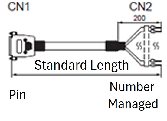 DSUB Connector Series | 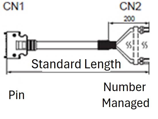 SCSI Connector Series |
| Connector Type | 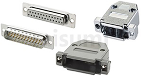 DSUB Connector | 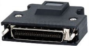 SCSI Connector |
| Model Specifications | 44-pin, 15-pin | 50-pin, 26-pin |
Specifications Overview
Original driver IO control harness, suitable for MISUMI original drivers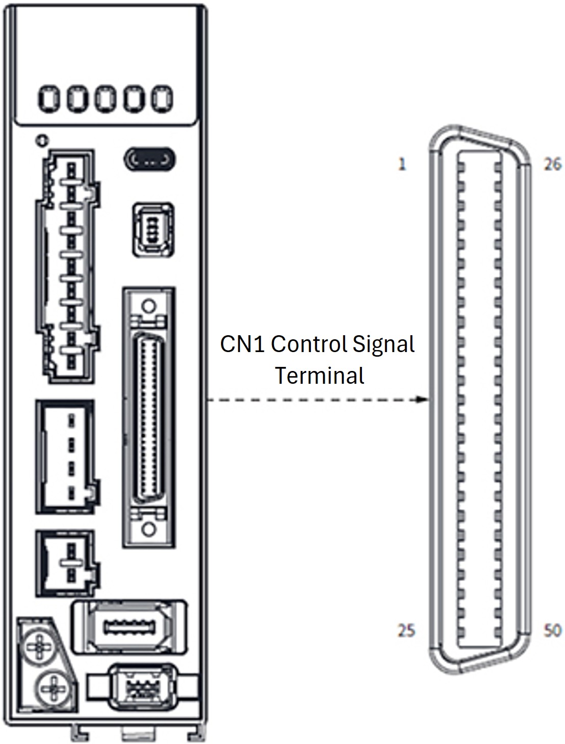
E-DHAS□□P-F Series Servo Driver Control Signal Terminal CN1 Diagram
E-SCSI-50PIN-1
E-DHAS□□E-F Series Servo Driver Control Signal Terminal CN1 Diagram
E-SCSI-26PIN-1
Servo Driver Control Signal Terminal CN1 Diagram
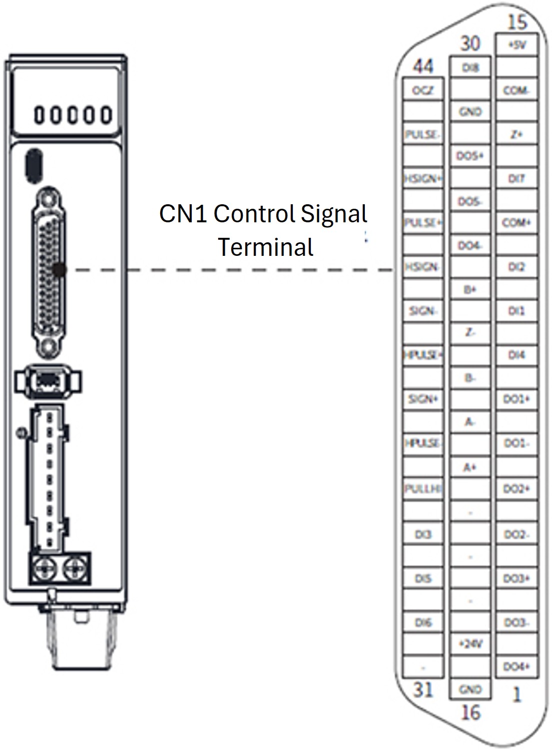
E-DB-44PIN-1
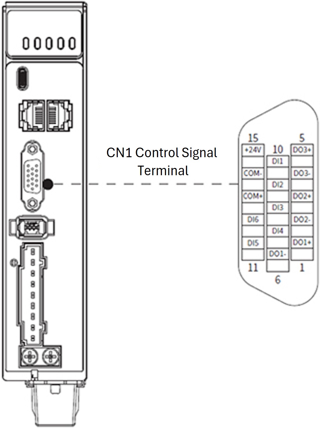
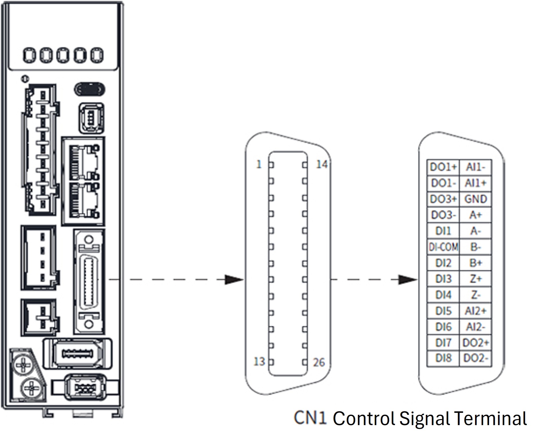
E-DB-15PIN-1
Servo Driver Control Signal Terminal CN1 Diagram

E-DHAS□□P-F Series Servo Driver Control Signal Terminal CN1 Diagram
E-SCSI-50PIN-1

E-DHAS□□E-F Series Servo Driver Control Signal Terminal CN1 Diagram
E-SCSI-26PIN-1

Servo Driver Control Signal Terminal CN1 Diagram
E-DB-44PIN-1

E-DB-15PIN-1
Servo Driver Control Signal Terminal CN1 Diagram
Specification Table
| Part Number | Outline Diagram | Number of PINs | Connector Type | Standard Length L (mm) | Cable Specification | Compatible Servo Motor Driver |
| E-DB-44PIN-1 | | 44 | DSUB Connector | 1000±30 | 28AWG | E-DFAS□□P-E (Pulse) |
| E-DB-15PIN-1 | 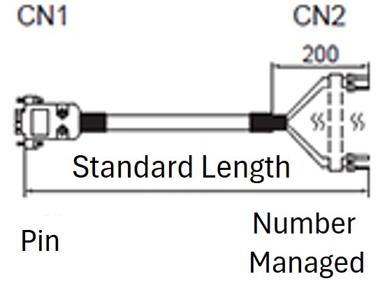 | 15 | DSUB Connector | 1000±30 | 28AWG | E-DFAS□□E-E (EtherCat Bus) |
| E-SCSI-50PIN-1 | | 50 | SCSI Connector | 1000±30 | 28AWG | E-DHAS□□P-F (Pulse) |
| E-SCSI-26PIN-1 | 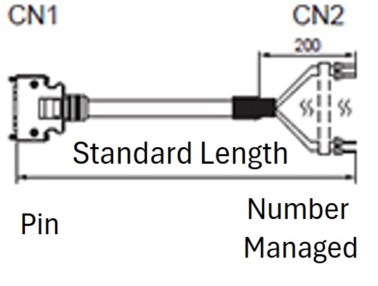 | 26 | SCSI Connector | 1000±30 | 28AWG | E-DHAS□□E-F (EtherCat Bus) |
Pin Definition (for MISUMI Driver Models)
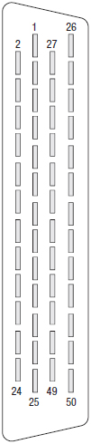
E-SCSI-50PIN-1
E-SCSI-26PIN-1
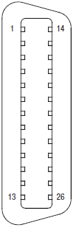
E-DB-44PIN-1
E-DB-15PIN-1
| Illustration | Pin | Pin Definition | Default Function | Function Description | Pin | Pin Definition | Default Function | Function Description |
| (Plug Solder Side) | ||||||||
 | 1 | PUL +24 | Pulse Command Input | Low-speed pulse direction command input method: PUL+ and PUL-: 5 V differential input (500KHz) DIR+ and DIR-: 5 V differential input (500KHz) PUL+24 and PUL-: 24 V single-ended input (200KHz) DIR+24 and DIR-: 24 V single-ended input (200KHz) | 37 | DO3+ | ALM+ | Servo Alarm Output |
| 3 | PUL+ | Pulse Command Input | 36 | DO3- | ALM- | |||
| 4 | PUL- | Pulse Command Input | 39 | DO4+ | INP1+ | Positioning End Output | ||
| 2 | DIR+24 | Direction Command Input | 38 | DO4- | INP1- | |||
| 5 | DIR+ | Direction Command Input | 41 | DOCOM | Output | General Output Common Terminal (Maximum current 50 mA, Maximum voltage 30 V) | ||
| 6 | DIR- | Direction Command Input | 12 | DO5 | ZSP | Zero Speed Detection Output | ||
| 44 | PULSH+ | High-speed Pulse Command Input | 4 MHz high-speed pulse command input, 5 V differential input | 40 | DO6 | TLC | Output under torque limitation | |
| 45 | PULSH- | High-speed Pulse Command Input | 14 | Analog Input 1 | AI1 | Speed command or speed limit input positive (0 to ±10 V) | ||
| 46 | SIGNH+ | High-Speed Direction Command Input | 4 MHz high-speed direction command input, 5 V differential input | 15 | GND | GND | Analog Ground | |
| 47 | SIGNH- | High-Speed Direction Command Input | 16 | Simulated Input 2 | Al2 | Torque Command / Forward Torque Limit Input (0 to +10 V) | ||
| 13 | GND | GND | Internal | 17 | GND | GND | Analog Ground | |
| 7 | DI-COM | Input | General Input Common Terminal | 18 | Simulated Input 3 | AI3 | Torque Command / Negative Direction Torque Limit Input (–10 to 0 V) | |
| 8 | DI1 | NOT | Negative direction drive input prohibited | 42 | AO1 | IM | Analog Monitor Output 1 (Configurable Monitoring Signal) | |
| 9 | DI2 | POT | Forward drive input prohibited | 43 | AO2 | SP | Analog Monitor Output 2 (Configurable Monitoring Signal) | |
| 26 | DI3 | No configuration | Not Provided | 21 | A+ | Differential Output | Encoder Frequency Division Output Phase A | |
| 27 | DI4 | GAIN | Gain Switch Input | 22 | A- | Differential Output | ||
| 28 | DI5 | DIV1 | Command Frequency Division/Multiplication Input Switching | 48 | B+ | Differential Output | Encoder Frequency Division Output B Phase | |
| 29 | DI6 | SRV-ON | Servo Enable Input | 49 | B- | Differential Output | ||
| 30 | DI7 | CL | Deviation Counter Reset Input | 23 | Z+ | Differential Output | Encoder Frequency Division Output Z Phase | |
| 31 | DI8 | A-CLR | Alarm Clear Input | 24 | Z- | Differential Output | ||
| 32 | DI9 | C-MODE | Control Mode Switch Input | 25 | GND | GND | Internal | |
| 33 | DI10 | INH | Command Pulse Input Disabled | 19 | OCZ | Z Phase Output | Z phase output (open collector) | |
| 11 | DO1+ | BRK-OFF+ | External Brake Release Output | 20 | GND | GND | Internal | |
| 10 | DO1- | BRK-OFF- | 50 | FG Shield Ground | FG | - | ||
| 35 | DO2+ | SRDY+ | Servo Ready Output | Shell | - | FG | Frame Grounding | |
| 34 | DO2- | SRDY- |
E-SCSI-26PIN-1
| Illustration | Pin Number | Pin Definition | Signal | Function Description (Default Function) | Pin Number | Pin Definition | Signal | Function Description (Default Function) |
| (Plug Solder Side) | ||||||||
 | 6 | DI-COM | Input | General Input Common Terminal | 3 | DO3+ | ALM+ | Alarm Output |
| 5 | DI1 | No configuration | General Input 1 | 4 | DO3- | ALM- | ||
| 7 | DI2 | POT | Forward drive input prohibited | 17 | A+ | Differential Output | Frequency-divided Output Phase A | |
| 8 | DI3 | NOT | Negative direction drive input prohibited | 18 | A- | Differential Output | ||
| 9 | DI4 | HOME-SWITCH | Return to Origin Switch Input | 20 | B+ | Differential Output | Frequency-divided Output B Phase | |
| 10 | DI5 | No configuration | General Input 5 | 19 | B- | Differential Output | ||
| 11 | DI6 | No configuration | General Input 6 | 21 | Z+ | Differential Output | Divided Frequency Output Z Phase | |
| 12 | DI7 | No configuration | General Input 7 | 22 | Z- | Differential Output | ||
| 13 | DI8 | No configuration | General Input 8 | 16 | GND | Signal Ground | Signal Ground | |
| 1 | DO1+ | BRK-OFF+ | External Brake Release Signal Output | 14 | AI1- | Simulated Input 1- | Analog Input 1 | |
| 2 | DO1- | BRK-OFF- | 15 | Al1+ | Simulated Input 1+ | |||
| 25 | DO2+ | SRDY+ | Servo Ready Signal Output | 23 | AI2+ | Simulated Input 2+ | Analog Input 2 | |
| 26 | DO2- | SRDY- | 24 | AI2- | Simulated Input 2- | |||
| Shell | - | FG | Frame Grounding |
E-DB-44PIN-1
| Illustration | Function | Pin | Pin Definition | Default Function | Function Description | Function | Pin | Pin Definition | Default Function | Function Description |
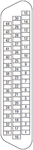 | Position Command | 41 | PULSE+ | Low-speed Pulse Command Input | Low-speed pulse command input method: ● Differential input (5 V) ● Open collector (24 V) Low-speed pulse and direction command input method: PULSE+ and PULSE-: 5 V differential input (500 kHz) SIGN+ and SIGN-: 5 V differential input (500 kHz) PULLHI and PULSE-: 24 V single-ended input (200 kHz) PULLHI and SIGN-: 24 V single-ended input (200 kHz) | General Input/Output | 30 | DI8 | HOME Switch | Home Switch |
| 7 | DO1+ | SRDY+ | Servo Ready Output | |||||||
| 6 | DO1- | SRDY- | ||||||||
| 5 | DO2+ | INP1+ | Positioning End Output | |||||||
| 43 | PULSE- | Low-speed Pulse Command Input | 4 | DO2- | INP1- | |||||
| 37 | SIGN+ | Low-speed Direction Command Input | 3 | DO3+ | BRK-OFF+ | Brake output | ||||
| 39 | SIGN- | Low-speed Direction Command Input | 2 | DO3- | BRK-OFF- | |||||
| 35 | PULLHI | Open collector 24 V input common terminal | 1 | DO4+ | ALARM+ | Alarm Output | ||||
| 26 | DO4- | ALARM- | ||||||||
| 38 | HPULSE+ | High-speed Pulse Command Input | 4 MHz high-speed pulse command input, 5 V differential input | 28 | DO5+ | HOME-OK+ | Home completed output | |||
| 36 | HPULSE- | High-speed Pulse Command Input | 27 | DO5- | HOME-OK- | |||||
| 42 | HSIGN+ | High-Speed Direction Command Input | 4 MHz high-speed direction command input, 5 V differential input | Frequency division output | 21 | A+ | Encoder Frequency Division Output Phase A | Differential output, quadrature divided pulse output signals for A and B. | ||
| 40 | HSIGN- | High-Speed Direction Command Input | 22 | A- | ||||||
| Universal | 17 | +24 V | Internal 24 V power supply | Internal 24 V power supply, voltage range +20 to 28 V, maximum output current 200 mA. Cannot be used as a brake power supply. | 25 | B+ | Encoder Frequency Division Output B Phase | |||
| 14 | COM- | 23 | B- | |||||||
| General Input/Output | 11 | COM+ | DI input terminal common | DI input terminal common | 13 | Z+ | Encoder Frequency Division Output Z Phase | Differential output, motor Z signal output | ||
| 9 | DI1 | POT | Forward drive input prohibited | 24 | Z- | |||||
| 10 | DI2 | NOT | Negative direction drive input prohibited | 44 | OCZ | Encoder Frequency Division Output Z Phase | Z-phase open collector output signal | |||
| 34 | DI3 | INH | Command Pulse Input Disabled | 29 | GND | Z-phase signal collector output signal ground | Z-phase signal collector output signal ground | |||
| 8 | DI4 | A-CLR | Alarm Clear Input | Universal | 15 | +5 V | Internal 5 V power supply | Internal 5 V power supply, maximum output current 200 mA. | ||
| 33 | DI5 | SRV-ON | Servo Enable Input | 16 | GND | |||||
| 32 | DI6 | No configuration | - | Shell | - | Enclosure | Frame Grounding | |||
| 12 | DI7 | No configuration | - |
E-DB-15PIN-1
| Illustration | Function | Pin | Pin Definition | Default Function | Function Description |
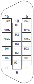 | Universal | 15 | +24 V | Internal 24 V power supply | Internal 24 V power supply, voltage range +20 to 28 V, maximum output current 200 mA. (The built-in 24 V power supply of the driver is not for use as the motor brake power supply; otherwise, it may trigger overload protection of the internal power supply.) |
| 14 | COM- | ||||
| General Input/Output | 13 | COM+ | DI input terminal common | DI input terminal common | |
| 10 | DI1 | POT | Forward drive input prohibited | ||
| 9 | DI2 | NOT | Negative direction drive input prohibited | ||
| 8 | DI3 | Home Switch | Return to Origin Home Switch Input | ||
| 7 | DI4 | EXT 2 | Probe 2 | ||
| 11 | DI5 | EXT 1 | Probe 1 | ||
| 12 | DI6 | No configuration | No default function assigned, can be configured as needed | ||
| 1 | DO1+ | SRDY+ | Servo Ready Output | ||
| 6 | DO1- | SRDY- | |||
| 3 | DO2+ | ALM+ | Alarm Output | ||
| 2 | DO2- | ALM- | |||
| 5 | DO3+ | BRK-OFF+ | Brake | ||
| 4 | DO3- | BRK-OFF- |
Related Products