E-DFAS Series Economy AC Servo Drivers

Brand :
MISUMI
Caution
- Since the battery kit E-AAS-BATBOX has not yet been released, it cannot be used with Absolute. Please contact us for information regarding the kit's release date.
Product Description
MISUMI AC Servo Motor which is applicable E-MASH1 and E-MASH2, E-MASS2 Motors.
Selection software
Click here to download the offline selection tool now
1.For the use of Incremental Encoders
2.For the use of Absolute Encoder

Model:E-CASTC2M Length:1.8m
No need to connect to a power supply, simply connect the driver to the computer using the debugging cable to monitor
and modify parameters with the EDrive debugging software.
-> Go to Control Cable Products
Click here to download the offline selection tool now
Related Material
MISUMI Driver EDrive Debugging Software Click here to download now
MISUMI Driver Quick Start Manual. Click to Download:
>> E-DFASxxE-F (EtherCAT type)
>> E-DFASxxP-F ( Pulse + RS485 type)
MISUMI Driver Product Manual. Click to Download:
>> E-DFAS_E-F (EtherCAT type)
>> E-DFAS_P-F ( Pulse + RS485 type)
Cables For MISUMI Servo Motors and Driver
>>Power Cable / Encoder Cable / Debuggin Cable / Battery Kit
I/O Cables For MISUMI Driver
>>IO Cable
Model Identification

1.For the use of Incremental Encoders
| Part Number | ①Type | ②Rated Power (W) | ③Control Type | ④Driver Spec | Remark |
| E-DFAS01P | E-DFAS | 01: 100W | P: Pulse+RS485 Bus | E: Standard Function | Battery is not required |
| E-DFAS04P | 04: 400W | ||||
| E-DFAS08P | 08: 750W | ||||
| E-DFAS10P | 10: 1000W | ||||
| E-DFAS01E | 01: 100W | E: EtherCAT Bus | |||
| E-DFAS04E | 04: 400W | ||||
| E-DFAS08E | 08: 750W | ||||
| E-DFAS10E | 10: 1000W |
2.For the use of Absolute Encoder
| Part Number | ①Type | ②Rated Power (W) | ③Control Type | ④Driver Spec | Remark |
| E-DFAS01P | E-DFAS | 01: 100W | P: Pulse+RS485 Bus | E: Standard Function | Battery Kit is required E-AAS-BATBOX |
| E-DFAS04P | 04: 400W | ||||
| E-DFAS08P | 08: 750W | ||||
| E-DFAS10P | 10: 1000W | ||||
| E-DFAS01E | 01: 100W | E: EtherCAT Bus | |||
| E-DFAS04E | 04: 400W | ||||
| E-DFAS08E | 08: 750W | ||||
| E-DFAS10E | 10: 1000W |
Driver Specifications
| Driver Model | E-DFAS□□P | E-DFAS□□E |
| Type | Pulse | EtherCAT |
| Rated output power | Single-phase AC 200V~240V, ±10%, 50/60Hz | |
| Maximum output current | Maximum current 21A; Rated current 7A | |
| Pulse input | Supported | Not Supported |
| EtherCAT | Not Supported | Supported |
| Auto tuning | Supported | |
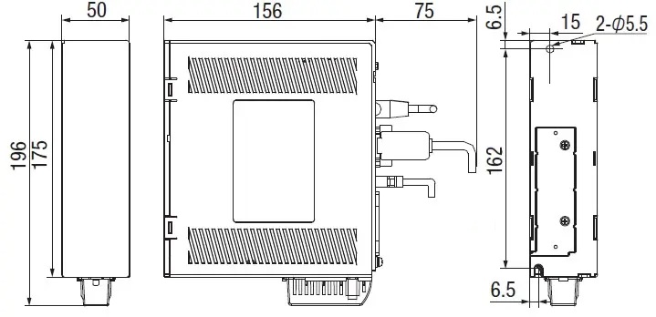
Dimensional Drawing(Unit: mm)
100W & 400W 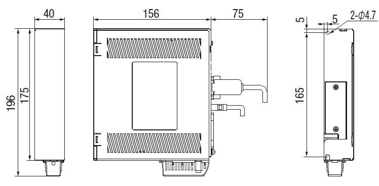
750W & 1000W 
E-DFAS01P(E)、E-DFAS04P(E)

E-DFAS08P(E)、E-DFAS10P(E)
Specification Table
| Driver Model | E-DFAS01P | E-DFAS04P | E-DFAS08P | E-DFAS10P | E-DFAS01E | E-DFAS04E | E-DFAS08E | E-DFAS10E |
| Rated output power (W) | 100 | 400 | 750 | 1000 | 100 | 400 | 750 | 1000 |
| Rated output current (Arms) | 1.2 | 3.5 | 5.5 | 7.0 | 1.2 | 3.5 | 5.5 | 7.0 |
| Maximum output current (Arms) | 3.4 | 10.1 | 16.9 | 21.0 | 4.8 | 9.5 | 16.6 | 21.0 |
| Regenerative braking resistor resistance value (Ω) | - | - | 50 | 50 | - | - | 50 | 50 |
| Regenerative braking resistor power of resistor (W) | - | - | 75 | 75 | - | - | 75 | 75 |
| Cooling mode | Natural Cooling | Natural Cooling | Natural Cooling | Natural Cooling | ||||
Motor And Compatible Driver
| Motor Model | Pulse Driver (Economy series) | EtherCAT Driver (Economy series) | Motor Frame Size (mm) | Power (W) | Electromagnetic Brake | Power Supply Voltage |
| E-MASH1-0401 | E-DFAS01P | E-DFAS01E | 40 | 100 | Not Provided | AC220V |
| E-MASH1-0401B | Provided | |||||
| E-MASH1-0602 | E-DFAS04P | E-DFAS04E | 60 | 200 | Not Provided | |
| E-MASH1-0602B | Provided | |||||
| E-MASH1-0604 | 400 | Not Provided | ||||
| E-MASH1-0604B | Provided | |||||
| E-MASH1-0808 | E-DFAS08P | E-DFAS08E | 80 | 750 | Not Provided | |
| E-MASH1-0808B | Provided | |||||
| E-MASH1-0810 | E-DFAS10P | E-DFAS10E | 1000 | Not Provided | ||
| E-MASH1-0810B | Provided |
Connection Diagram

Cables Specifications

Model:E-CASTC2M Length:1.8m
No need to connect to a power supply, simply connect the driver to the computer using the debugging cable to monitor
and modify parameters with the EDrive debugging software.
CN1 Control Circuit Connection Diagram
To select this product-> Go to Control Cable Products
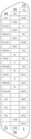
-DFAS□□P
Pulse control

Model:E-DB-44PIN-1
Note: The driver includes only the CN1 connector; customers need to perform the soldering themselves.
The E-DB-44PIN-1 cable is a compatible cable sold separately.
DB 44PIN terminal pin functions
 | Pin No. | Pin Definition | Default Function | Function Description | Pin No. | Pin Definition | Default Function | Function Description |
| 41 | PULSE+ | Low-speed pulse command input | Low-speed pulse command input mode: ·Differential input(5V) ·Open collector(24V) Low-speed pulse/direction command input mode: PULSE+ and PULSE-:5VDifferential input(500kHz) SIGN+ and SIGN-:5VDifferential input(500kHz) PULLHI and PULSE-:24Vsingle-ended input(200kHz) PULLHI and SIGN-:24Vsingle-ended input(200kHz) | 7 | DO1+ | SRDY+ | Servo ready output | |
| 43 | PULSE- | Low-speed pulse command input | 6 | DO1- | SRDY- | |||
| 37 | SIGN+ | Low-speed direction command input | 5 | DO2+ | INP1+ | In-position output | ||
| 39 | SIGN- | Low-speed direction command input | 4 | DO2- | INP1- | |||
| 35 | PULLHI | Open collector 24V input common | 3 | DO3+ | BRK-OFF+ | Brake output | ||
| 38 | HPULSE+ | High-speed pulse command input | 4MHz High-speed pulse command input,5VDifferential input | 2 | DO3- | BRK-OFF- | ||
| 36 | HPULSE- | High-speed pulse command input | 1 | DO4+ | ALARM+ | Alarm output | ||
| 42 | HSIGN+ | High-speed direction command input | 4MHzHigh-speed direction command input,5VDifferential input | 26 | DO4- | ALARM- | ||
| 40 | HSIGN- | High-speed direction command input | 28 | DO5+ | HOME-OK+ | Homing complete output | ||
| 17 | +24V | 24V internal power supply | 24V internal power supply, voltage range: +20~28V, maximum output current: 200mA. Cannot be used as brake power supply | 27 | DO5- | HOME-OK- | ||
| 14 | COM- | 21 | A+ | Encoder frequency dividing output phase A | Differential output, orthogonal frequency dividing pulse output signal of phase A/B. | |||
| 11 | COM+ | DI input terminal common | DI input terminal common | 22 | A- | |||
| 9 | DI1 | POT | Forward drive prohibit inpu | 25 | B+ | Encoder frequency dividing output phase B | ||
| 10 | DI2 | NOT | Reverse drive prohibit input | 23 | B- | |||
| 34 | DI3 | INH | Signal inhibit | 13 | Z+ | Encoder frequency dividing output phase Z | Differential output, motor's phase Z signal output | |
| 8 | DI4 | A-CLR | Alarm clear input | 24 | Z- | |||
| 33 | DI5 | SRV-ON | Servo enable ON input | 44 | OCZ | Encoder frequency dividing output phase Z | Phase Z open collector output signal | |
| 32 | DI6 | No configuration | - | 29 | GNDOutput signal ground of phase Z signal collector | Output signal ground of phase Z signal collector | ||
| 12 | DI7 | No configuration | - | 15 | +5V | 5V internal power supply | 5V internal power supply, maximum output current: 200mA. | |
| 30 | DI8 | HOME-Switch | Home switch | 16 | GND | |||
| Shell | - | Casing | Frame grounding |
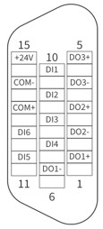
E-DFAS□□E
EtherCAT Control
Model:E-DB-15PIN-1
Note: The driver includes only the CN1 connector; customers need to perform the soldering themselves.
The E-DB-15PIN-1 cable is a compatible cable sold separately.
DB 15PIN terminal pin functions
 | Pin No. | Pin Definition | Default Function | Function Description | |
| 15 | +24V | 24V internal power supply | 24V internal power supply, voltage range: +20-28V, maximum output current: 200mA. (The driver's built-in 24V power supply cannot be used as the motor's brake power supply, otherwise the over-current protection of the built-in power supply will be triggered.) | ||
| 14 | COM- | ||||
| 13 | COM+ | DI input terminal common | DI input terminal common | ||
| 10 | DI1 | POT | Forward drive prohibit input | ||
| 9 | DI2 | NOT | Reverse drive prohibit input | ||
| 8 | DI3 | HomeSwitch | Home switching input | ||
| 7 | DI4 | EXT 2 | Contact probe 2 | ||
| 11 | DI5 | EXT 1 | Contact probe1 | ||
| 12 | DI6 | No configuration | No default function assigned, configurable | ||
| 1 | DO1+ | SRDY+ | Servo ready output | ||
| 6 | DO1- | SRDY- | |||
| 3 | DO2+ | ALM+ | Alarm output | ||
| 2 | DO2- | ALM- | |||
| 5 | DO3+ | BRK-OFF+ | Brake | ||
| 4 | DO3- | BRK-OFF- | |||