Chains Nominal No.25/Joint Link

Caution
- Download Free! >>Economy Series Catalog ver2023 (TH-EN)_Part06 CLICK here
Product Description
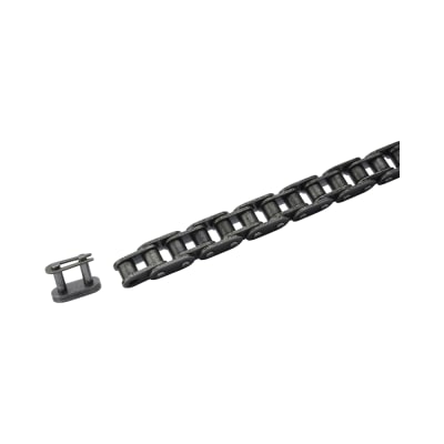
- Chains Nominal No.25 / Joint Link C-CHE25 series from MISUMI.
- This chain type is economy series of standard chains.
- Chain nominal No. is 25 while pitch No. is 6.35mm.
- Max. Allowable Tension of chain is 0.64 kN.
- The number of chain links is 240 links, circumference length is 1,524mm.
- Chains are made of steel.
- This series is ISO Standard 04C (ANSI25) roller chain and can be used in combination with our 25B series sprocket.
Economy Chains Nominal No.25/Joint Link
- Standard roller chains designed for efficient and durable performance.
- Precision engineering for a reliable and accurate fit.
- Max allowable tension for demanding applications.
- Ideal for use with compatible sprockets and systems.
- Stocked for quick shipping, ensuring fast turnaround for your projects.

MISUMI Standard

Cheaper Price

Product Variety

3D CAD Support
Product Overview of Chains
All Chains used on machinery, mechanisms and machines are referred to as industrial Chains.
The roller part of the Chains meshes with the tooth part of the sprocket and transmits power as tension.
■Only sprockets and Chains with the same specifications can be used in combination.
This series is ISO Standard 04C (ANSI25) roller Chains, and can be used in combination with our 25B series sprocket.
Do not use it with European Standard 04B sprocket, which may cause the Chains sprocket mechanism to fail to function properly!
■ Product Composition of Chains

Dimensional Drawing of Chains

 Material of Chains: Steel
Specifications Overview of Chains
This series is ISO Standard 04C (ANSI25) roller Chains, and can be used in combination with our 25B series sprocket.
Do not use it with European Standard 04B sprocket, which may cause the Chains sprocket mechanism to fail to function properly!

Product Feature of Chains
1. Multi-tooth load bearing, safe and reliable;
2. Flexible transmission, absorbing shock and vibration;
3. Large center distance range, low manufacturing and mounting accuracy requirements;
4. Compared with belt drive, the transmission ratio is accurate and the transmission efficiency is higher, suitable for high temperature.
■Two main purposes of the Chains:
1. Connect the motor for transmission
2. Place the workpiece directly or indirectly on the Chains for transfer
Example Use of Chains
A mechanism that can convert motor power into roller rotation by combining multiple sprockets and Chains

A Chains conveyor frame with high versatility using flat profiles and chain guides

A mechanism used to mount accessories on the Chains, and extract and transport workpieces

Precautions of Chains
Do not use it with European Standard 04B sprocket, which may cause the Chains sprocket mechanism to fail to function properly!
If you need to cut the Chains by yourself, please confirm whether the chain link to be cut is an inner link or an outer link.
If it is a single section after being cut off, it may need to be used with an offset link head.
Usage Method of Chains
■Horizontal
Even when the two axes are arranged horizontally, the rotation direction of the axis must be considered.
The examples (2) and (3) in the figure show that when the chain is stretched, the disengagement between the sprocket teeth and the chain is not smooth and may bite.
In particular, the upper and lower Chains in (3) will contact each other, so an idler is required.

If the Chains is stretched, slack as shown in (5) will occur, and
when a small sprocket is used on the lower side, the chain may fall off. Therefore, please use it at an angle of 60 or less as shown in (4).
When it is necessary to use it vertically due to the mechanism or space, it is recommended to put the large sprocket on the lower side, and
use the idler on the outside or inside as shown in (6).

Deflection is generally about 4% of the shaft spacing, and about 2% in the following cases.
a. Vertical transmission or close to vertical transmission
b. Shaft spacing is more than 1m
c. When frequent heavy load starting and stopping are required
d. When reverse rotation is required

If a tension adjuster is mounted on the tension side or slack side of the Chains to provide initial tension in advance, it will eliminate vibration and reduce noise during operation.

Related Products of Chains
 |
| Sprocket 25B |