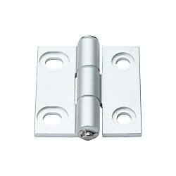
Aluminum Hinges Slotted Hole
Brand :
MISUMI
Caution
- Download Free! >>Economy Series Catalog ver2023 (TH-EN)_Part19 CLICK here
Product Description
Hinges are an economy item, The price is cheaper than the MISUMI standard product.They offer a wide variety of sizes to choose from.
[Feature]
● Number of Holes : 2 holes per side (Circles and Slotted Holes)
● Mounting Distance (mm.) : 21, 30.5 and 42
● Material :
- Body : Aluminum A6063-T5
- Bushing: Polyacetal
● Surface Treatment: Alumite Treatment
[Application]
Hinges can be used with common combinations of aluminum profiles for smaller doors and windows on machines.
Product Overview of Flat Hinges
Economy series Aluminum Flat Hinges Slotted hole type
This series products are aluminum slotted hole type butterfly Flat Hinges, with clear anodizing surface treatment.
Note: This product is mounted with slotted hole on one side. It can be fixed using an ultra-low head bolt when processing the slotted hole. Please pay attention to the depth information of processing hole. See the Specification Table fordetails.
Usage Method of Flat Hinges
According to the weight of the door body where the Flat Hinges is mounted, the load-carrying capacity of the Flat Hinges can be calculated.
Determine the utilization direction first, and calculate according to the length and width of the door body
Determine the utilization direction first, and calculate according to the length and width of the door body
| Utilization Method of Flat Hinges | Lengthwise Utilization | Lateral Utilization | |
| A=2XB | A≠2XB | - | |
 | 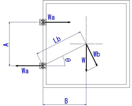 | 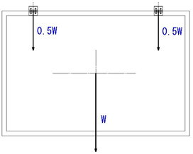 | |
| Allowable Load Calculation Formula | Allowable Load =W | Allowable Load =W(B/A)*2 | Allowable Load =W |
Specifications Overview of Flat Hinges
Product Material and Surface Treatment Overview Flat Hinges:
| Type of Flat Hinges |  Material Material |  Surface Treatment Surface Treatment |
| C-HHYSNA | A6063-T5 Bushing: Polyacetal | Alumite Treatment |
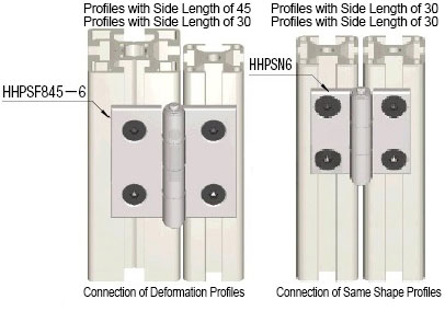
Example Use of Flat Hinges
Depending on the profile to be fixed, the selectable Flat Hinges specifications can be determined by the allowable load weight.
For details, refer to the following table for the applicable hinge model.
Flat Hinges common combinations of aluminum profiles can be confirmed and found from the table below.
For details, refer to the following table for the applicable hinge model.
Flat Hinges common combinations of aluminum profiles can be confirmed and found from the table below.
| Representative Dimensional Drawing | Type of Matching Profile | Suitable Profile | * Allowable Load | Product Model | Surface Treatment | Mounting Pitch S mm | |
| KG | N | ||||||
 | Profile of the Same Size on Two Sides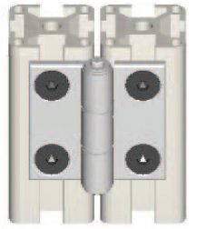 | Link 20/20 Profile | 8 | 78 | C-HHFL5 | Clear Anodized | 21 |
| C-HHBFL5 | Black Anodized | ||||||
| 10 | 98 | HHPSN5 | Clear Anodized | ||||
| HHPBSN5 | Black Anodized | ||||||
| 20 | 196 | C-HHDL5 | Clear Anodized | ||||
| C-HHBDL5 | Black Anodized | ||||||
| Link 30/30 Profile | 8 | 78 | C-HHFL6 | Clear Anodized | 32 | ||
| C-HHBFL6 | Black Anodized | ||||||
| 10 | 98 | HHPSN6 | Clear Anodized | ||||
| HHPBSN6 | Black Anodized | ||||||
| 20 | 196 | C-HHDL6 | Clear Anodized | ||||
| C-HHBDL6 | Black Anodized | ||||||
| Link 40/40 Profile | 8 | 78 | C-HHFL8 | Clear Anodized | 42 | ||
| C-HHBFL8 | Black Anodized | ||||||
| 10 | 98 | HHPSN8 | Clear Anodized | ||||
| HHPBSN8 | Black Anodized | ||||||
| 20 | 196 | C-HHDL8 | Clear Anodized | ||||
| C-HHBDL8 | Black Anodized | ||||||
| Link 45/45 Profile | 12 | 118 | C-HHFL8-45 | Clear Anodized | 47 | ||
| C-HHBFL8-45 | Black Anodized | ||||||
| 15 | 147 | HHPSN8-45 | Clear Anodized | ||||
| HHPBSN8-45 | Black Anodized | ||||||
| 30 | 294 | C-HHDL8-45 | Clear Anodized | ||||
| C-HHBDL8-45 | Black Anodized | ||||||
Profile with Different Sizes on Two Sides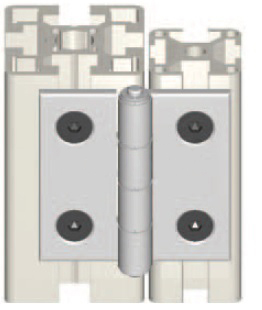 | Link 20/30 Profile | 8 | 78 | C-HHFLS6-5 | Clear Anodized | 26.5 | |
| 10 | 98 | HHPSF6-5 | |||||
| 20 | 196 | C-HHDLS6-5 | |||||
| Link 30/40 Profile | 8 | 78 | C-HHFLS8-5 | 31.5 | |||
| 10 | 98 | HHPSF8-5 | |||||
| 20 | 196 | C-HHDLS8-5 | |||||
| Link 20/45 Profile | 8 | 78 | C-HHFLS845-5 | 34 | |||
| 10 | 98 | HHPSF845-5 | |||||
| 20 | 196 | C-HHDLS845-5 | |||||
| Link 20/40 Profile | 12 | 118 | C-HHFLS8-6 | 37 | |||
| 15 | 147 | HHPSF8-6 | |||||
| 30 | 294 | C-HHDLS8-6 | |||||
| Link 30/45 Profile | 12 | 118 | C-HHFLS845-6 | 39 | |||
| 15 | 147 | HHPSF845-6 | |||||
| 30 | 294 | C-HHDLS845-6 | |||||
Precautions of Flat Hinges
To install the Flat Hinges on the panel, etc., it is recommended to choose the nut for butterfly hinge. For details, you can search TYPE: HHPNT or HHPFNT in the website to choose according to the size requirements.
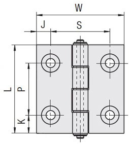
Dimensional Drawing of Flat Hinges
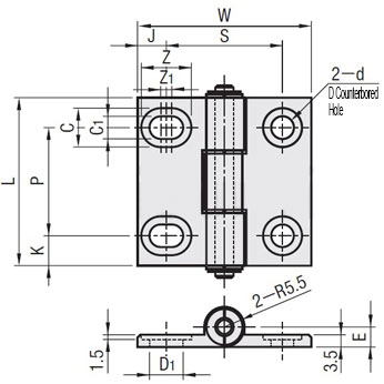
Refer to the Specification Table below for detailed product dimensions
Specification Table of Flat Hinges
| Part Number | * Allowable Load | Weight g | L | W | K | P | J | S | d Through hole | D Countersunk hole | D1 | C | C1 | Z | Z1 | E | ||
| TYPE | No. | kg | N | |||||||||||||||
| C-HHYSNA | 5 | 8 | 78 | 24 | 47 | 35.4 | 11 | 25 | 7.2 | 21 | 5.5 | 11 | 7 | 11 | 5.5 | 12.5 | 1.5 | 5.5 |
| 6 | 31 | 48 | 8.5 | 30 | 8 | 30.5 | 6.5 | 13 | 9.5 | 13 | 6.5 | 15.8 | 2.8 | 6 | ||||
| 8 | 51 | 63 | 62 | 13 | 37 | 10 | 42 | 11.5 | 18 | 5 | ||||||||