Cam Followers Crown,Hex Socket
Caution
- Download Free! >>Economy Series Catalog ver2023 (TH-EN)_Part08 CLICK here
- Products with d ≥ 10 are being gradually switched over to specifications with through holes in the L dimension. Please take this into account prior to purchasing.
Product Description
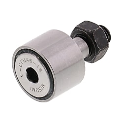
・ Product type: Cam Followers Hex socket, Crown shape roller type
・ This is an economy item; The price is cheaper than the MISUMI standard product.
・ Roller material: Made of SUJ2
・ Outer roller diameter D (Ø) [mm]: 10, 12, 13, 16, 19, 22, 26, 30, 32, 35, 40, 52, 62, 72, 80, 85, 90
・ Roller width B [mm]: 7, 8, 9, 11, 12, 14, 18, 20, 24, 29, 35
・ Stud Screw Nominal size: M3 x 0.5, M4 x 0.7, M5 x 0.8, M6 x 1, M8 x 1.25
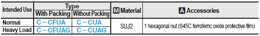
・ Model type: C-CFUA, C-CFUAG, C-CUA, CFUAG, CUAG
Economy Cam Followers Crown
- Manufactured from premium SUJ2 steel. Provides exceptional durability and wear resistance for long-lasting performance in demanding applications.
- Comes with multiple stud screw size options.
- Features a hex socket on the head for secure fastening. Simplifies installation and adjustment, reducing setup time and effort.
- Roller with various diameter and width options
- Crown shape design improves load distribution and reduces friction. Enhances the efficiency of the cam follower, leading to better overall performance and longevity.


MISUMI Standard

Cheaper Price

Product Variety

3D CAD Support
Roller Followers Product Overview
Cam follower is a high-performance bearing with shaft, which has a needle-shaped roller called needle roller mounted inside.
The needle roller has the function of improving the rotating capacity and can withstand high-speed rotation.
In addition, the outer ring is designed with a thicker wall than ordinary bearings, and can also be used in places subject to impact loads or heavy loads.
_002.jpg)
Roller Followers Product Feature
2. Ideal for places subject to loads!
3. Also suitable for high speed rotation!
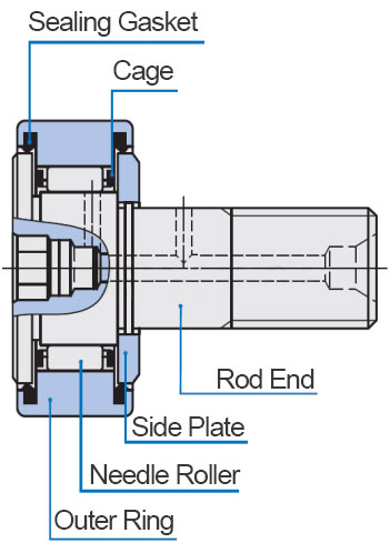
Standard Cam Follower Structure
[ ! ] No grease replenishing hole is provided.
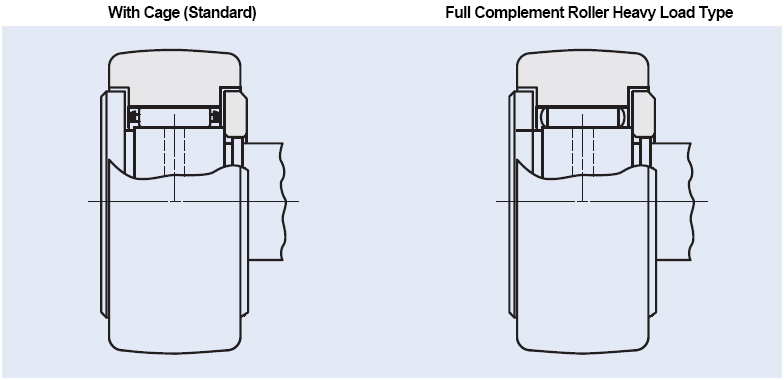
Roller Guide Mode
The cam follower with cage is suitable for applications with low friction coefficient and high rotation speed, and the full complement roller cam follower is suitable for applications with high rotation speed and heavy load.
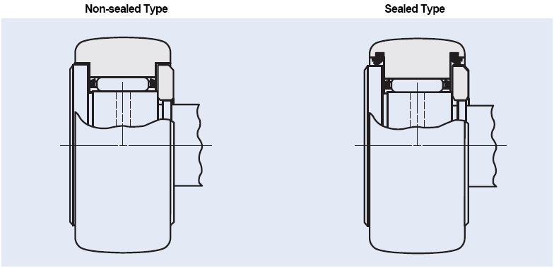
Roller Followers Structure of Sealing Part
For the non-sealed type bearing, the gap between the outer ring and the end rod peripheral ring and between the outer ring and the side plate is small, thus forming a labyrinth. For the sealed type bearing, a sealing gasket is mounted in the shielded type labyrinth, thus preventing intrusion of foreign matter.
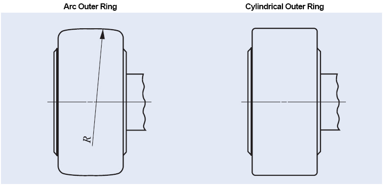
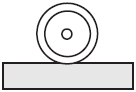
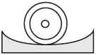
Outer Ring O.D. Shape
The bearing with spherical outer ring can alleviate uneven load caused by installation problems. The contact area between the bearing with arc outer ring and the slide rail surface is large, suitable for slide rail surfaces with large load or low hardness.
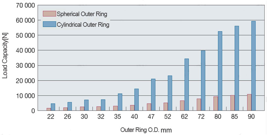
Slide Rail Load Capacity Comparison
Roller Followers Specification Table
Roller Followers Dimensional Drawing
Arc Type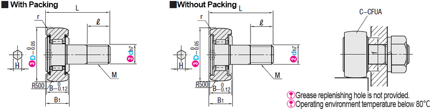
| Part Number |  D D | M×pitch | B | B1 | L | D1 | ℓ | r | Basic Rated Load | Maximum Allowable Load (kN) | Rail Load Capacity (kN) | Rotation Speed Limit (rpm) | Weight (g) | |||||||||
 Type Type |  dh7 Tolerance dh7 Tolerance | Normal Low Dust | Heavy Load | Normal Low Dust | Heavy Load | Normal Low Dust | Heavy Load | Normal Low Dust | Heavy Load | Normal Low Dust | ||||||||||||
| C (Dynamic) kN | Cor(Static) kN | C (Dynamic) kN | Cor (Static) kN | With Packing | Without Packing | With Packing | ||||||||||||||||
| (With Packing) C-CFUA C-CFUAG (Without Packing) C-CUA C-CUAG | 3 | 0 -0.01 | 10 | 3×0.5 | 7 | 8 | 17 | 7 | 5 | 0.3 | 1.18 | 0.94 | 2.5 | 2.61 | 0.29 | 0.5 | 0.3 | 0.56 | 26320 | 37600 | 25000 | 4.5 |
| 4 | 0 -0.012 | 12 | 4×0.7 | 8 | 9 | 20 | 8.5 | 6 | 1.65 | 1.64 | 3.5 | 3.8 | 0.62 | 0.92 | 0.38 | 0.72 | 20720 | 29600 | 19000 | 7.5 | ||
| 5 | 13 | 5×0.8 | 9 | 10 | 23 | 9.6 | 7.5 | 0.15 | 2.51 | 2.22 | 4.5 | 5.3 | 1.14 | 1.64 | 0.42 | 0.8 | 16240 | 23200 | 15000 | 10.5 | ||
| 6 | 16 | 6×1.0 | 11 | 12.2 | 28 | 12.5 | 8 | 3.15 | 3.3 | 4.9 | 6.5 | 1.69 | 2.11 | 0.86 | 1.08 | 14000 | 14000 | 3800 | 18.5 | |||
| 8 | 0 -0.015 | 19 | 8×1.25 | 32 | 15 | 10 | 3.5 | 3.9 | 5.4 | 7.9 | 3.78 | 4.73 | 1.1 | 1.37 | 11000 | 11000 | 3100 | 28.5 | ||||
| 10 | 22 | 10×1.0 | 12 | 13.2 | 36 | 17.5 | 12 | 0.3 | 4.5 | 5.2 | 6.2 | 9.1 | 4.65 | 5.81 | 1.34 | 1.67 | 8000 | 8000 | 2600 | 45 | ||
| 26 | 5.1 | 6.2 | 7.3 | 11.3 | 1.83 | 2.06 | 2600 | 60 | ||||||||||||||
| 12 | 0 -0.018 | 30 | 12×1.5 | 14 | 15.2 | 40 | 23 | 13 | 0.6 | 6.8 | 8.4 | 9.5 | 14.6 | 7.5 | 9.37 | 1.96 | 2.62 | 5500 | 5500 | 2100 | 95 | |
| 32 | 7.1 | 8.9 | 10 | 15.8 | 9.37 | 2.19 | 2.86 | 2100 | 105 | |||||||||||||
| 16 | 35 | 16×1.5 | 18 | 19.6 | 52 | 27.6 | 17 | 9.8 | 14.1 | 12.8 | 23 | 13.84 | 17.3 | 2.51 | 3.2 | 3600 | 3600 | 1600 | 170 | |||
| 18 | 40 | 18×1.5 | 20 | 21.6 | 58 | 31.5 | 19 | 1 | 10.9 | 15.5 | 14.8 | 26.5 | 20.88 | 26.1 | 2.98 | 3.85 | 2900 | 2900 | 1400 | 250 | ||
| 20 | 0 -0.021 | 52 | 20×1.5 | 24 | 25.6 | 66 | 36.5 | 21 | 16.7 | 29 | 22.6 | 48 | 25.68 | 32.1 | 6.58 | 7.65 | 2400 | 2400 | 2300 | 460 | ||
| 24 | - | 62 | 24×1.5 | 29 | 30.6 | 80 | 44 | 25 | 1.1 | 26 | 48 | 34 | 75 | 61 | 98 | - | - | 1900 | - | 1100 | 770 | |
| 72 | 28 | 53 | 36.5 | 85 | 67 | 111 | - | - | - | 787 | ||||||||||||
| 30 | - | 80 | 30×1.5 | 35 | 37 | 100 | 53 | 32 | 39 | 77 | 49.5 | 117 | 9900 | 153 | - | - | 1300 | - | 850 | 1608 | ||
| 85 | 51 | 123 | 10400 | 162 | - | - | - | 1678 | ||||||||||||||
| 90 | 41 | 83 | 52 | 129 | 10600 | 169 | - | - | - | 1975 | ||||||||||||
 kgf=N×0.101972
Roller Followers Specifications Overview
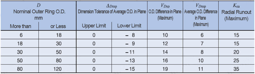
Allowable Tolerance
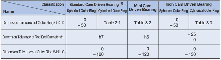
Allowable Tolerance of Outer Ring and Allowable Value
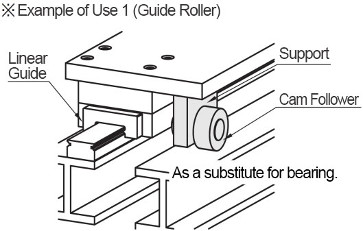
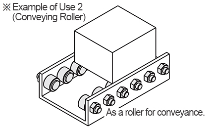
Roller Followers Example of Use
Attaching Method
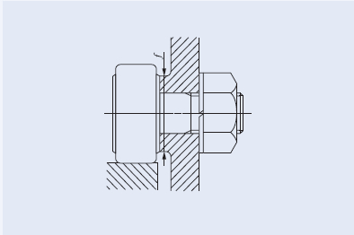
Do not use a hammer to directly hit the flange of the cam bearing during installation, otherwise it will cause poor rotation or fracture. Use a hex socket wrench or a slotted screwdriver.
Secure the hexagon socket or screwdriver slot for fixing, and then turn the nut with a wrench to tighten.
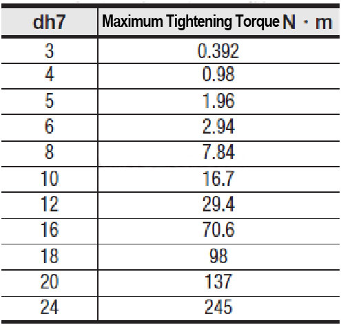
Bolt Tightening Torque
Do not exceed the maximum screw tightening torque when installing the cam follower. Otherwise, the threaded portion may be damaged.
Roller Followers Precautions
· Attention should be paid to the fact that impact can cause functional damage, even if it is not visible.
· Cam followers are suitable for radial loads and less suitable for thrust loads, so avoid using methods such as applying thrust loads.
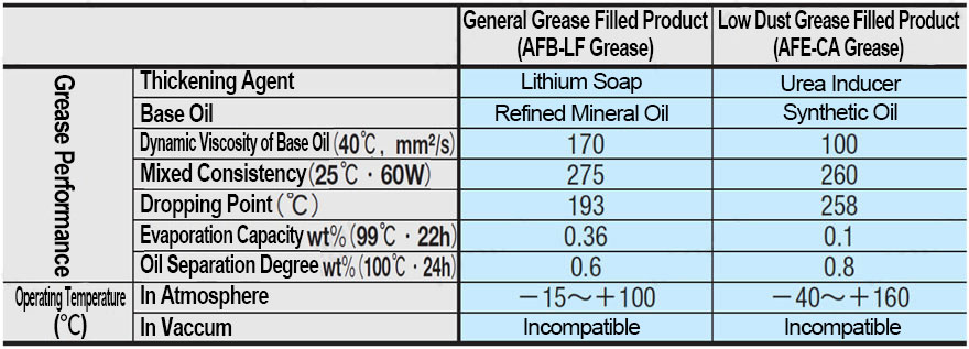
· Some cam followers are not filled with grease due to different sizes.
Please refer to the table below and add proper amount of grease to the products that are not filled with grease before use.
Cam Follower Grease Performance and Service Temperature