Aluminum Profile Foot Base - Multi-Size Mounting Plate, M8-M16

Caution
Product Description
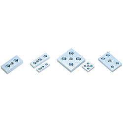
Mounting Plates or Foot Bases For Aluminum Profile alway use it when connecting casters and adjusters. They offer a wide variety of sizes to choose from.
[Feature]
● Applicable Aluminum Profile MISUMI Series 5,6,8 and 8-45
● Nominal of Thread : M8, M10, M12 and M16
● Material : SUS304 and SS400
● Surface treatment : Trivalent Chromate only SS400
[Application]
Mounting Plates or Foot Bases are commonly used in industrial machinery to install with aluminum profiles
Dimensional Drawing of Foot Bases for Aluminum Extrusions

GLF8
The aluminum frame to which it is attached requires additional machining to add end taps.
| Foot Bases for Aluminum Extrusions Type | Material | Surface Treatment |
| HLF・GLF | SS400 | Trivalent Chromate |
| HLFS | SUS304 | − |
Specification Table of Foot Bases for Aluminum Extrusions
| Foot Bases for Aluminum Extrusions Model | − | M |
| HLF6-3060 | − | 10 |
・To check the latest price, please click the "Check Price" button after confirming the model number.
| Compatible Series | Foot Bases for Aluminum Extrusions Model | Adjuster pad screw hole M (coarse) | Shape pattern | A | B | W | W1 | V | E | T | Countersink MA | Mass kg HLF(GLF) | Mounting bolts (sold separately) | Applicable frame end face tapping | |||||||||
| Type | Foot Bases for Aluminum Extrusions | ||||||||||||||||||||||
| HLFS | bolt | Quantity | |||||||||||||||||||||
| 5 series groove width 6mm | HLF5 | 2040 | 8 | AA | 20 | 40 | 20 | − | − | − | 9 | 5 | 0.05 | M5-15 | 2 | LTP / RTP / TPW (LHP / RHP / HPW are not applicable) | |||||||
| 2550 | 8 | twenty five | 50 | twenty five | 12 | 8 | 0.07 | M8−25 | |||||||||||||||
| 2060 | 8 | AC | 20 | 60 | 20 | 9 | 5 | 0.06 | M5-15 | 3 | |||||||||||||
| 2080 | 8 | AA | 80 | 60 | 0.1 | 2 | |||||||||||||||||
| 4040 | 8 | 10 | 12 | A.B. | 40 | − | 20 | 0.09 | 4 | ||||||||||||||
| 404020 | 12 | AE | 20 | 10 | 15.5 | 14.5 | 12 | 0.08 | − | M5-20 | 2 | ||||||||||||
| 404020A | 12 | AG | 0.06 | 2 | |||||||||||||||||||
| 4060 | 12 | AJ | 60 | 40 | 40 | 10 | 20 | − | 9 | 0.14 | M5-15 | 4 | |||||||||||
| 4080 | 12 | AD | 80 | 60 | − | 0.21 | |||||||||||||||||
| 6 series groove width 8mm | HLF6 | 3060 | 10 | 12 | 16 | AA | 30 | 60 | 30 | − | − | − | 12 | 8 | 0.13 | M8−25 | 2 | ||||||
| 3090 | 12 | AC | 90 | 0.24 | 3 | ||||||||||||||||||
| 30120 | 12 | AA | 120 | 90 | 0.31 | 2 | |||||||||||||||||
| 5050 | 10 | 12 | A.B. | 50 | − | 20 | 0.28 | 4 | |||||||||||||||
| 50100 | 10 | 12 | AD | 100 | 50 | 70 | 20 | 0.42 | |||||||||||||||
| 100100 | 16 | 20 | A.B. | − | − | 0.9 | |||||||||||||||||
| 6060 | 10 | 12 | 16 | 60 | 30 | 0.28 | |||||||||||||||||
| 606030 | 12 | AF | 30 | 15 | 15 | 0.18 | − | 3 | |||||||||||||||
| 606030A | 12 | AH | 0.16 | 2 | |||||||||||||||||||
| 6090 | 16 | AD | 90 | 60 | 60 | 30 | − | 0.47 | 4 | ||||||||||||||
| 60120 | 16 | 120 | 90 | 0.63 | |||||||||||||||||||
| 8 series 8-45 series groove width 10mm | HLF8 | 4080* | 12 | 16 | AA | 40 | 80 | 40 | − | − | − | 16 | 12 | 0.31 | M12-30 | 2 | |||||||
| 40160 | 16 | 160 | 120 | 0.79 | |||||||||||||||||||
| 4590* | 16 | 45 | 90 | 45 | 0.427 | M12-20 | |||||||||||||||||
| 45180 | 16 | 20 | 180 | 135 | 0.94 | ||||||||||||||||||
| 50100* | 16 | AA | 50 | 100 | 50 | 12 | 0.55 | ||||||||||||||||
| 8080 | 12 | 16 | 20 | A.B. | 80 | − | 40 | 8 | 0.73 | M8-30 | 4 | ||||||||||||
| twenty four | 30 | A.B. | 19 | 0.95 | M8-30 | 4 | |||||||||||||||||
| 808040 | 16 | AF | 40 | 20 | 20 | 16 | 12 | 0.38 | − | M12-30 | 3 | ||||||||||||
| 808040A | 16 | AH | 0.35 | 2 | |||||||||||||||||||
| 80160 | 16 | 20 | AD | 160 | 80 | 120 | 40 | − | 8 | 1.56 | M8-30 | 4 | |||||||||||
| 9090 | 16 | 20 | A.B. | 90 | − | 45 | − | 0.95 | |||||||||||||||
| twenty four | 30 | 19 | 1.21 | M8-30 | 4 | ||||||||||||||||||
| 909045 | 16 | AF | 90 | 45 | 22.5 | 22.5 | 16 | 12 | 0.54 | − | M12-20 | 3 | |||||||||||
| 909045A | 16 | AH | 90 | 0.51 | 2 | ||||||||||||||||||
| 90180 | 16 | 20 | AD | 180 | 90 | 135 | 45 | − | 16 | 8 | 1.99 | M8-30 | 4 | ||||||||||
| GLF8 | 9090 (High rigidity type) | 20 | A.B. | 90 | − | 45 | − | − | − | 16 | 12 | 0.95 | − | M12-25 | 4 | ||||||||
| twenty four | 30 | 19 | 1.21 | M12-30 | |||||||||||||||||||
| 100100* | 20 | 100 | 50 | 16 | 1.12 | M12-20 | |||||||||||||||||
| twenty four | 30 | 19 | 1.49 | M12-30 | |||||||||||||||||||
The aluminum frame to be attached to must have an end face tapped.
[ ! ]Mounting bolts are not included.
[ ! ]Foot Bases for Aluminum Extrusions marked with an * in the frame column of the specifications table can also be used with high-rigidity aluminum frames.
Installation Example of Foot Bases for Aluminum Extrusions
Shape pattern AA | Shape pattern AB | Shape pattern AC |
![]() | ![]() | ![]() |
Shape pattern AD | Shape pattern AE | Shape Pattern AF |
![]() | ![]() | ![]() |
Shape pattern AG | Shape pattern AH | Shape pattern AJ |
![]() | ![]() | ![]() |
[ ! ]Mounting bolts are not included.
Related Parts of Foot Bases for Aluminum Extrusions
| Hexagonal socket head bolt (cap bolt) | Caster | Adjuster | ||
| Category Page | Hexagonal socket head bolt (cap bolt) | Casters (caster type: screw-in type) | Adjuster | |
| Representative products of Foot Bases for Aluminum Extrusions | Hexagonal Socket Head Bolt - Stainless Steel, Small Box, Sold Individually - | Hexagonal Socket Head Bolt - Iron, Sold Individually - | Screw-in casters, light to medium load, HSGN□ | Adjuster metal standard type |
| image | ![]() | ![]() | ![]() | ![]() |


