Solid State/Timer H3YN

Caution
Product Description
Timer is shaped similarly to the H3Y, and supports multiple time ranges and operational modes.
[Features]
· EN61812-1 compatible, conforms to the CE mark.
· Supports multiple time ranges with switch-over between 4 ranges.
· Supports multiple operational modes providing 4 functions in 1 device.
· MY type relay and terminal compatible.
· Compatible with the EN standard, so OK for export to Europe.
· A semi-multi power supply voltage range greatly reduces the number of maintenance supplies kept in stock.
[Applications]
· The timer acts as control equipment, switching the output signal at the preset time after the start signal is input.
Solid-State Timer Specifications

H3YN external appearance
Solid-State Timer Performance
| Format | Series H3YN-2/-4 | Series H3YN-21/-41 | |
|---|---|---|---|
| Variations In Operating Time | ±1% or less (at maximum scale time) (±1% ±10 ms or less at 1 s range) | ||
| Set Error | ±10% ±50 ms or less (at maximum scale time) | ||
| Recovery Time | 0.1 s or less (including recovery during operation) | ||
| Voltage Effect | ±2% or less (at maximum scale time) | ||
| Temperature Effect | ±2% or less (at maximum scale time) | ||
| Insulation Resistance | 100 MΩ or more (measurement at 500 V DC megger) | ||
| Withstand Voltage | 2,000 V AC, 50/60 Hz, 1 min (between conductive part terminal and exposed non-charging metal part, excluding the terminal screw part) 2,000 V AC, 50/60 Hz, 1 min (between control output and operation circuit) 2,000 V AC, 50/60 Hz, 1 min (2-pole type between different pole contacts) 1,500 V AC, 50/60 Hz, 1 min (4-pole type between different pole contacts) 1,000 V AC, 50/60 Hz, 1 min (between discontinuous contacts) | ||
| Vibration | Endurance | 10 to 55 Hz, half amplitude 0.75 mm, 3 directions, 1 h each | |
| Malfunction | 10 to 55 Hz, half amplitude 0.5 mm, 3 directions, 10 min each | ||
| Shock | Endurance | 1,000 m/s2, 6 directions, 3 times each*1 | |
| Malfunction | 100m/s2, 6 directions, 3 times each | ||
| Life | Mechanical | 10 million operations or more (no load, switching frequency 1,800 operations/h) | |
| Electrical | 2-pole, 500,000 operations or more (250 V AC, 5 A, resistive load, switching frequency 1,800 operations/h) (room temperature) 4-pole, 200,000 operations (100,000 operations or more for -Z) or more (250 V AC, 3 A, resistive load, switching frequency 1,800 operations/h) (room temperature)*2 | ||
| Impulse Voltage | 3 kV between power supply terminals; however, 1 kV for 12 V DC, 24 V DC, 48 V DC and 24 V AC, 4.5 kV between the conductive part terminal and exposed non-charging metal part; however, 1.5 kV for 12 V DC, 24 V DC, 48 V DC and 24 V AC | ||
| Noise Resistance | Square-wave noise by noise simulator (pulse width 100 ns/1 μs rise 1 ns) ±1.5 kV | ||
| Electrostatic Strength | 4 kV (Malfunction), 8 kV (Destruction) | ||
| Protective Structure | IP40 | ||
| Mass | Approx. 50g | ||
*1. Condition when carrying out impact resistance testing with the timer alone.
*2. Check the electrical life curve.
Solid-State Timer Dimensional Drawing
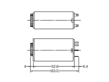
Series H3YN-2, H3YN-21 dimensional drawing A
Series H3YN-2, H3YN-21 dimensional drawing B
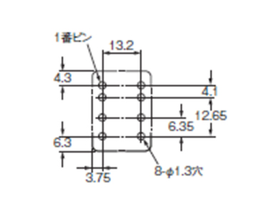
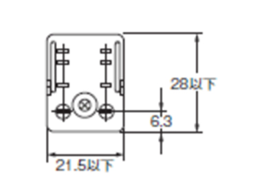
Series H3YN-2, H3YN-21 mounting hole processing dimensional drawing
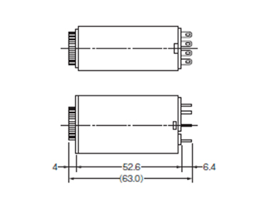
Series H3YN-4, H3YN-41, H3YN-4-Z dimensional drawing A
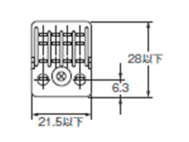
Series H3YN-4, H3YN-41, H3YN-4-Z dimensional drawing B
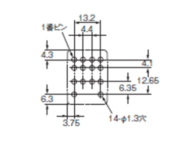
Series H3YN-4, H3YN-41, H3YN-4-Z mounting hole processing dimensional drawing