Microminiature Circular Connectors, HR25/HR25A Series

Caution
Product Description
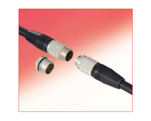
Circular, microminiature high-density type connectors.
[Features]
· Secure screw-lock types and smooth push-pull lock types are available.
· Two types of termination are available: crimp and solder types. Direct-to-board type receptacles are also available.
· Plug, jack, receptacle and reverse type contacts are also available.
· Featuring a metal-shell design ideal for equipment that requires EMI shielding countermeasures
[Applications]
· Useful for various types of wiring work.
Wide Variety of Small, Low-Profile, High-Performance Circular Connectors
The connector's metal shell design is the optimal choice for devices that require EMI shielding
Main Features of HR25 Series Microminiature Circular Connectors
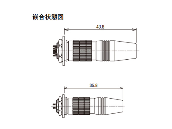
Diagram of mated state
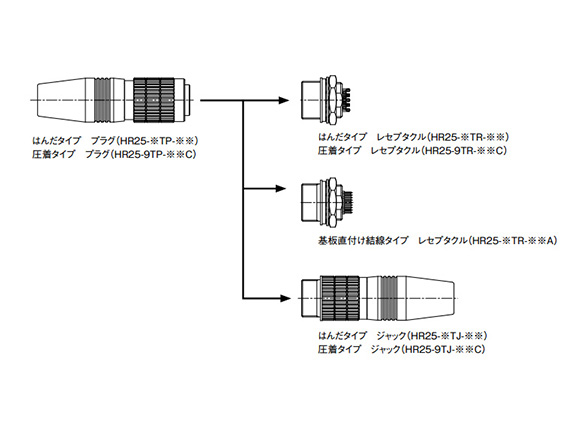
Connector Combination Diagram
Product Standards
| Rating | Rated Current | 1 A | Operating Temperature Range | -25 to 85°C |
|---|---|---|---|---|
| Rated voltage | 30 V AC, 42 V DC | Storage temperature range | -10 to 60°C |
| Item | Standard | Conditions |
|---|---|---|
| 1. Contact resistance | 30 mΩ or less | Measure at 1 A DC |
| 2. Insulation resistance: | 1,000 MΩ or more | Measure at 100 V DC |
| 3. Withstand voltage | There shall be no flashover or dielectric breakdown | 100 V AC for 1 min. |
| 4. Vibration resistance | There shall be no electrical discontinuity for 10 μs or greater | Test at 10 to 55 Hz/cycle, Single amplitude: 0.75 mm Three directions, 2 hours each. |
| 5. Shock | There shall be no electrical discontinuity for 11 μs or greater | Test at acceleration 490 m/s2, duration: 11 ms, 3 directions, 3 times each. |
| 6. Mating cycle | Contact resistance 50 mΩ or less | 1,000 times |
| 7. Temperature cycle | Insulation resistance 1,000 MΩ or more | Leave at -55°C: 30 mins. > Room temperature: 10 to 15 mins. > 85°C: 30 mins. >Room temperature: 10 to 15 mins. for a total of 5 cycles. |
| 8. Humidity resistance | Insulation resistance 5 MΩ or more (at high humidity) 50 MΩ or more (when dry) | Leave at temperature 40°C, humidity 90 to 95% for 96 hours. |
Product Materials/Processing
| Item | Materials | Finish | Note | |
|---|---|---|---|---|
| Plug jack | Outer shell | Zinc alloy | Nickel plating | - |
| Insulator | PPS resin | - | UL94V-0 | |
| Packing, bushing | Ethylene-propylene rubber | - | - | |
| Contacts | Phosphor bronze | Gold plating | - | |
| Receptacle | Outer shell | Zinc alloy | Nickel plating | - |
| Insulator | PPS resin | - | UL94V-0 | |
| Contacts | Phosphor bronze | Gold plating | - | |
| Gasket | Ethylene-propylene rubber | - | - | |
Product Wiring Procedure (Plug Side)
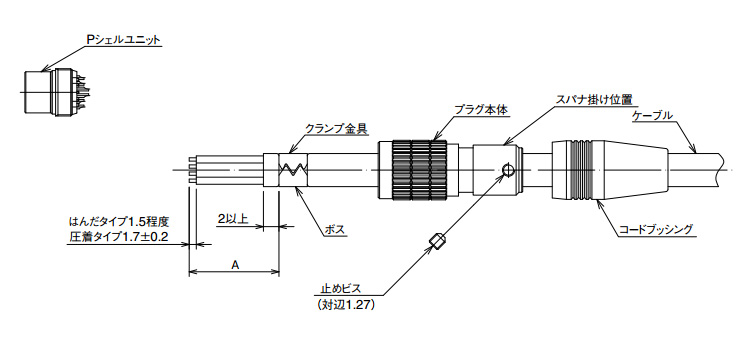
Cable Assembly Procedures (Plug Side) Outline Diagram
The outline of wiring work for this diagram uses the soldered type as an example. The jack side is also based on the work outline of the plug; however, the receptacle side does not require a special work outline and has been omitted because of this.
| Shell Size | Dimensions of Soldered Type A | Dimensions of Crimped Type A | Spanner Spacing | Tightening Torque |
|---|---|---|---|---|
| 7 | 10 mm | - | 8 mm | 1 N·m |
| 9 | 19 mm | 15 mm | 10 mm | 1 N·m |
Cable Assembly (Plug Side) Table-1
○ Work Procedure
Use cables with a nominal sectional area of 0.08 mm2 (28 AWG) or less at the finished outer diameters applicable for each size.2. First pass the cable bushing and the plug body in order over the cable, then cut the end at the dimensions indicated in the above diagram.
3. Mount the P shell unit in the wiring jig and perform the solder wiring.
4. Use the cable crimping jig (HR10A-TC-02) to fix the clamp fitting to the cable.
5. After performing the wiring, tighten the plug body to the threaded portion of the P shell unit using the specified torque (in Table-1 above.)
6. Tighten the set screw so that the tip of the set screw falls into one of the 2 bosses of the clamp fitting. The tightening torque of the set screw is from 0.3 to 0.4 N·m.
7. Put the cable bushing over the plug body to complete. The use of paint lock (e.g., Loctite 263 manufactured by HENKEL JAPAN LTD.) is recommended on the threaded portion to prevent loosening of the P shell unit.
Use cables with a nominal sectional area of 0.05 mm2 (30 AWG) or less at the finished outer diameters applicable for each size.
2. Crimp a suitable crimp terminal to the conductor portion of the cable, then fit into the housing of the P-shell unit.
Dimensional Drawing of Product Panel Mounting Hole
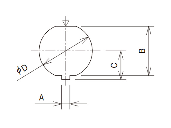
Dimensional Drawing of Panel Mounting Hole
Mounting hole dimensions are indicated as viewed from the receptacle engagement side
| Locking Method | Screw Lock Type | |||
|---|---|---|---|---|
| Diagram Symbols | Shell Size | |||
| Size 7 | Size 9 | |||
| A | 1.55 | +0.05 0 | 1.55 | +0.05 0 |
| B | 7.25 | +0.03 -0.02 | 9.25 | +0.03 -0.02 |
| C | 4.4 | +0.1 0 | 5.4 | +0.05 0 |
| D | 8 | +0.05 0 | 10 | +0.05 0 |
| Mounting panel thickness | 0.7 to 2 | 0.7 to 2 | ||
The ▽ mark indicates the engagement guide key position
Product Receptacle DIP Post Configuration Dimensions
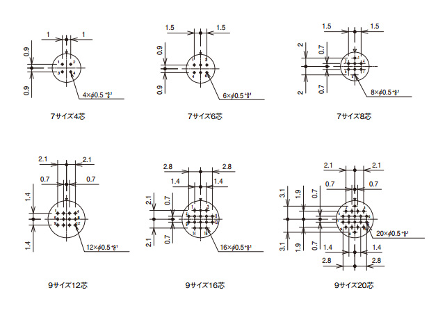
Receptacle DIP post configuration dimensions / Size 7, 4-conductors / Size 7, 6-conductors / Size 7, 8-conductors / Size 9, 12-conductors / Size 9, 16-conductors / Size 9, 20-conductors
Note
- 1. The above diagrams are viewed from the engagement side of the socket insert (i.e., the wiring side of the pin insert.)
- 2. The ▽ mark in the above diagrams indicates the engagement guide key position.
- 3. A tolerance of ±0.05 is recommended for non-specified dimensions.
Contact Position Arrangement and Main Functions
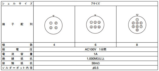
Contact configuration and main functions
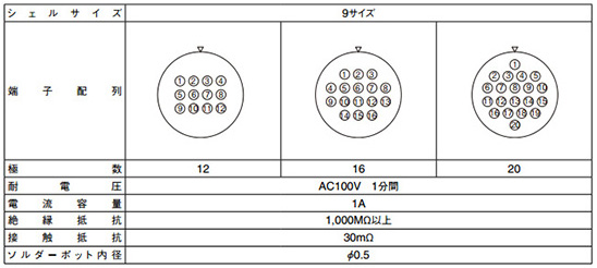
Note
- 1. The above diagrams are viewed from the engagement side of the socket insert (i.e., the wiring side of the pin insert.)
- 2. The ▽ mark in the above diagrams indicates the engagement guide key position.
- 3. The withstand voltage indicates the test voltage value. For regular use, the voltage used should be less than 30 V AC or 42 V DC.
- 4. The current capacity of the crimp terminals indicates the value when using wire of AWG#30.
- 5. The insulation resistance indicates a value when measured at 100 V DC.
Connector Usage Precautions
- 1. Make sure the power is off before mating or un-mating the connector.
- 2. Use connectors with socket (female) contacts at the power side of the circuit.
- 3. Make sure that the coupling is in the completely locked position.
- 4. Cable clamping, cable rotation, and other forces may vary with the cable construction. Make sure that your cable is suitable for use with these connectors before usage and production.