Corrosion-Resistant and Waterproof Circular Connector, JR-W Series

Caution
Product Description
Circular, waterproof connectors.
[Features]
· Waterproof performance: Equivalent to IP67 and IP68 when mated.
· IP67: left for 30 minutes at a water depth of 1 m.
· IP68: left for 14 days at a water depth of 2 m.
· Corrosion resistance: exterior shell is plated considering corrosion resistance for use in the various environments.
Circular Connectors With A Wide Variety of Shell Sizes and Contact Numbers
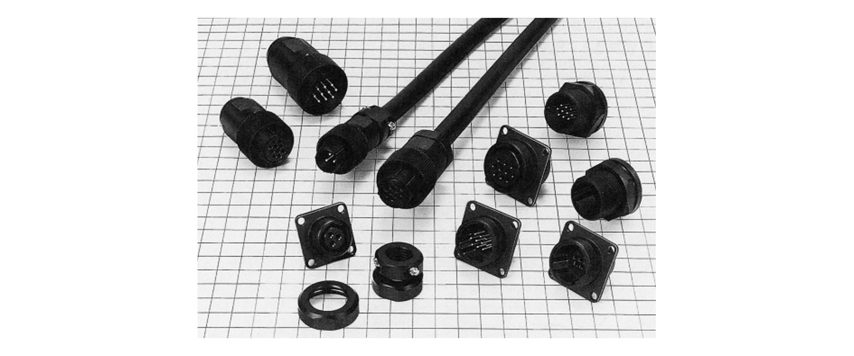
Can be used for the interfaces of machine tools, communications equipment, etc.
Main Features of JR-W Series Circular Corrosion-Resistant and Waterproof Connectors
Main Specifications
| Connector Type | Plug, receptacle, jack, accessories, other |
|---|---|
| Panel Mounting Method | Screw, bulkhead, bulkhead (rear mount) |
| Waterproof performance | IP68 |
| Number of Contacts | 16, 3, 5, 10, 7, 24, 4 |
| Contact Plating | Silver |
| Number of Matings and Un-Matings | 500, 100 |
| Rated Current | 10, 5, 30, 15 A |
| Rated Voltage (AC) | 250, 100, 200, 300 V AC |
| Rated Voltage (DC) | 350, 140, 280, 420 V DC |
| Opening Direction | Straight |
| Wiring Method | Solder, crimp |
| Locking Method | Screw fastening |
| Compatible Wire Size (AWG) Max. | AWG16, 20, 10, 12 |
| External Material | Metal |
| Operating Temperature Range (Max.) | 85℃ |
| Operating Temperature Range (Min.) | -25, -40°C |
Product Standards (1)
| Rating | Rated Current | Shell Size | Number of Contacts | Rated Current |
|---|---|---|---|---|
| 13 | 3 | 10 A | ||
| 5 | 5 A | |||
| 16 | 7 | 10 A | ||
| 10 | 5 A (crimp type 3 A) | |||
| 21 | 10 | 10 A | ||
| 16 | 5 A | |||
| 25 | 4 | 30 A | ||
| 16 | 10 A | |||
| 24 | 5 A (crimp type 3 A) |
| Rating | Rated Current | Shell Size | Number of Contacts | Rated Current |
|---|---|---|---|---|
| 13 | 3 | 100 V AC, 140 V DC | ||
| 5 | ||||
| 16 | 7 | 100 V AC, 140 V DC | ||
| 10 | ||||
| 21 | 10 | 100 V AC, 140 V DC | ||
| 16 | ||||
| 25 | 4 | 300 V AC, 420 V DC | ||
| 16, 24 | 100 V AC, 140 V DC |
| Rating | Operating Temperature Range | -25 to +85°C |
|---|---|---|
| Storage temperature range | -10 to +60°C |
Product Standards (2)
| Item | Standard | Conditions |
|---|---|---|
| 1. Contact resistance | 5 mΩ or less JR16-10-pin crimp type: 10 mΩ or less JR25-24-pin crimp type: 10 mΩ or less | Measure at 1 A DC |
| 2. Insulation resistance: | 1,000 MΩ or more JR25-4-Pin: 10,000 MΩ or more | Measure at 500 V DC |
| 3. Withstand voltage | There shall be no flashover or dielectric breakdown | 1,000 V AC for 1 min. JR25-4-pin: 3,000 V AC for 1 min. |
| 4. Vibration resistance | There shall be no electrical discontinuity for 10 μs or greater | Test at 10 to 55 Hz/cycle, Single amplitude: 0.75 mm Three directions, 2 hours each. |
| 5. Shock | There shall be no electrical discontinuity for 10 μs or greater | Test at acceleration 490 m/s2, duration: 11 ms, 6 axial directions, 3 times each. |
| 6. Mating cycle | Contact resistance 5 mΩ or less JR16-10-pin crimp type: 10 mΩ or less JR25-24-pin crimp type: 10 mΩ or less | 500 times |
| 7. Temperature cycle | Insulation resistance 1,000 MΩ or more JR25-4-pin: 10,000 MΩ or more | Leave at -40°C: 30 mins. > Room temperature: 10 to 15 mins. > 100°C: 30 mins.> Room temperature: 10 to 15 mins. for a total of 5 cycles. |
| 8. Humidity resistance | Insulation resistance 10 MΩ or more (at high humidity) 100 MΩ or more (when dry) JR25-4-pin: 100 MΩ or more (at high humidity) 1,000 MΩ or more (when dry) | Temperature: 40°C, relative humidity: 90 to 95%, left for 96 hours. |
| 9. Waterproofing | No water penetration inside connector | Leave at water depth of 1.8 m for 48 hours while mated with the applicable connector. |
Materials/Processing
| Part Name | Materials | Finish | Note |
|---|---|---|---|
| Exterior | Aluminum alloy, brass | Black chrome plating | - |
| Insulator | Phenolic resin, PPS resin | - | UL94V-0 |
| Contacts | Copper alloy | Silver plating | - |
| Waterproof packing | Nitrile rubber, silicone rubber | - | - |
Product Wiring Procedure (Plug Side)
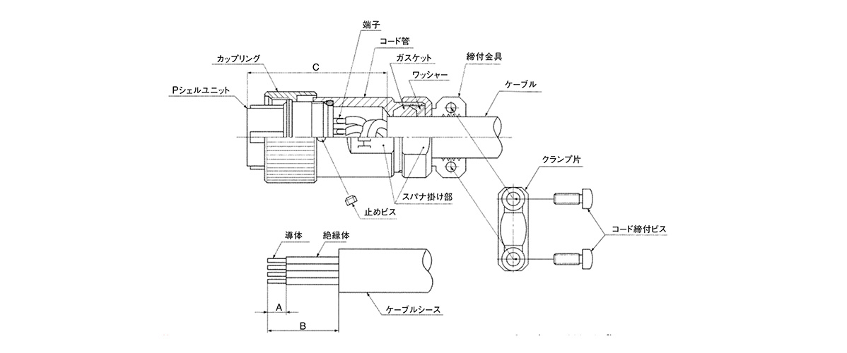
Wiring procedure (plug side) schematic
Work Procedure
1. Connector Disassembly
(1) To remove the plug, remove the set screw, fit an applicable receptacle to the P shell unit to fix, and remove the cord tube.
(2) To remove the cord clamp, remove the 2 cord tightening screws. (Note 1)
2. Wiring
2-1 Solder Type
(1) Use the cable so that the conductor can be soldered properly into the solder pot and with the applicable cable sheath diameter used for each cord clamp.
(2) After terminal processing the cable to the dimensions shown in Table-1, apply the fastening bracket, washer, gasket, cord tube, and coupling in that order to the cable in the direction shown in the above diagram.
(3) Solder the wires to connect the conductors to the terminals of the P shell unit. Shrinkable tube is recommended to be used at the connecting part because insulating performance might deteriorate due to solder whiskers or dewing. After connecting, adjust so that the dimensions of the C portion are satisfied. (Note 2)
2-2 Crimping Type
(1) Make sure to use a cable with the correct outer diameter for the cord clamp. It is also important that the conductor and its outer diameter are appropriate for the crimp contacts.
(2) After terminal processing the cable to the dimensions shown in Table-2, apply the fastening bracket, washer, gasket, cord tube, and coupling in that order to the cable in the direction shown in the above diagram.
(3) After crimping the applicable crimping contacts onto the conductor, insert the crimping contacts into the contact holes of the P-shell unit. After inserting, adjust so that the dimensions of the C portion are satisfied. (Note 2)
3. Connector Assembly
(1) Fit the connected P shell unit to the receptacle fixed with a vice or the like and insert into the coupling and cord tube. Torque the cord tube to the level as given in Table-3.
(2) Fit the gasket, washer and clamp. Torque the clamp to the level as given in Table-3 while ensuring the cable does not rotate.
(3) Torque the set screw to 0.2 to 0.25 N·m.
(4) Torque the cord tightening screw (two positions) to 0.65 to 0.7 N·m. (Note 1) (Note 3)
Note 1. Not required if a simple type cord clamp is used.
Note 2. Maintain these dimensions until assembly is complete.
Note 3. Cable clamping force, cable rotation force, and others aspects including waterproof performance may differ depending on the cable construction. Verify the suitability of the cable assembly before use or production.
Units: mm
| Shell Size | A | B | C |
|---|---|---|---|
| 13 | (3) | (12) | 37 or less |
| 16 | (3) | (14) | 39 or less |
| 21 | (3) | (17) | 42 or less |
| 25 | (3) | (20) | 45 or less |
Table-1 (solder type)
Units: mm
| Shell Size | Number of Contacts | A | B | C |
|---|---|---|---|---|
| 16 | 10 | 3.5 to 4 | (19) | 39 or less |
| 21 | 4 to 4.5 | (22) | 42 or less | |
| 16 | 3.5 to 4 | |||
| 25 | 24 | (25) | 45 or less |
Table-2 (crimp type)
Units: N·m
| Shell Size | Tightening torque |
|---|---|
| 13 | 2 to 2.5 |
| 16 | 3 to 3.5 |
| 21 | 4 to 4.5 |
| 25 | 5 to 5.5 |
Table-3
Contact Position Arrangement and Main Functions
- 1. Figures are views of contact arrays of the mating end of male connectors.
- *2 The withstand voltage indicates the test voltage value.
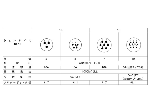
Shell sizes 13, 16
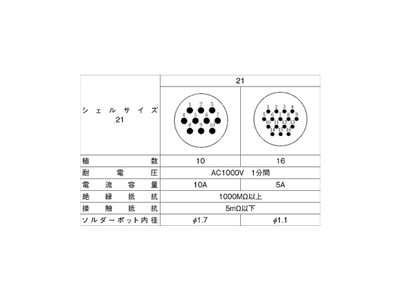
Shell size 21
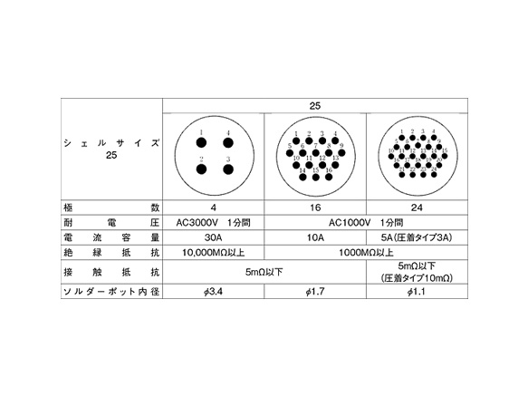
Shell size 25
Product Usage Precautions
- 1. Make sure the power is off before mating or un-mating the connector.
- 2. Use connectors with socket (female) contacts at the power side of the circuit.
- 3. Always use the screw lock function of the connector (state when tightened to maximum degree.)
- 4. Use connectors in combination with other waterproof types.