Round Miniature Waterproof Plastic Connectors (Push-Pull Lock Type), HR30 Series

Caution
Product Description
Small and circular waterproof connectors.
[Features]
· Made from plastic for a lighter weight.
· Waterproof structure when mated equivalent to IP67 and IP68.
· The push-pull lock enables smooth mating.
· Cable clamping is possible just by tightening the cord tube.
· Can be securely mated while being held in your hand.
· Multiple guide keys and the mating markings help prevent mis-insertion.
[Applications]
· Useful for various types of wiring work.
Features of HR30 Series Round Miniature Waterproof Plastic Connectors (Push-Pull Lock Type)
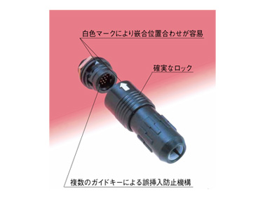
· Features white index marks which are used to quickly align the two interfaces for proper mating
· The secure lock mechanism ensures that locking can be performed while holding it in your hand
· The multiple guide keys help prevent erroneous insertion
Lock structural diagram
push-pull type (single-action lock)

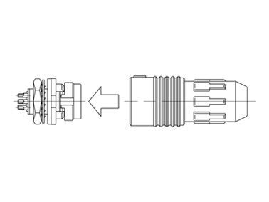
Mating state diagram
3- and 6-pin and 10- and 12-pin
Product Specifications
Product Standards
| Rating | Rated Current | 5 A (3-pin), 2 A (6-, 10-, 12-pin) | Operating Temperature Range | -25°C to 85°C |
|---|---|---|---|---|
| Rated voltage | 100 V AC, 140 V DC (3-, 6-pin), 30 V AC, 42 V DC (10-, 12-pin) | Storage temperature range | -10°C to 60°C |
| Item | Standard | Conditions | |
|---|---|---|---|
| 1. Contact resistance | 5 mΩ or less (3-pin) 15 mΩ or less (6-, 10-, 12-pin: solder type) 30 mΩ or less (6-, 12-pin: DIP type) | Measure at 1 A DC | |
| 2. Insulation resistance | 1,000 MΩ or more | Measure at 100 V DC. | |
| 3. Withstand voltage | There shall be no flashover or dielectric breakdown | 300 V AC for 1 min. | |
| 4. Vibration resistance | There shall be no electrical discontinuity for 10 μs or greater | Test at 10 to 55 to 10 Hz/cycle, Single amplitude: 0.75 mm, 5 mins./cycle Three-axial directions: 10 cycles each | |
| 5. Mating cycle | Contact resistance 10 mΩ or less (3-pin) Contact resistance 30 mΩ or less (6-, 10-, 12-pin: solder type) Contact resistance: 60 mΩ or less (6-, 12-pin: DIP type) | 1,000 times | |
| 6. Temperature cycle | Insulation resistance: 100 MΩ or more | -55°C: 30 mins. > Room temperature: 10 to 15 mins. > +85°C: 30 mins.> Room temperature: 10 to 15 Mins for 5 cycles | |
| 7. Humidity Resistance | Insulation resistance | 10 mΩ or more (at high humidity) 100 MΩ or more (when dry) | Temperature 40°C, Humidity 90 to 95%, 96 hours |
| 8. Waterproofing | No water penetration inside connector | Leave at water depth of 1 m for 30 minutes while mated with the applicable connector | |
Materials/Processing
| Item | Materials | Finish | Note | |||
|---|---|---|---|---|---|---|
| Plug | Exterior / Insulator | PPS resin (black) | UL94V-0 | |||
| PBT resin (black) | UL94V-0 | |||||
| Polyacetal resin (natural) | - | |||||
| Gasket | SIR/CR (red/black) | - | ||||
| Male terminal, female terminal | Brass, phosphor bronze, copper alloy | Gold plating | - | |||
| Spring | Stainless steel | - | ||||
| Receptacle | Exterior / Insulator | PPS resin (black) | UL94V-0 | |||
| Gasket | CR (black) | - | ||||
| Male terminal, female terminal | Brass, phosphor bronze, copper alloy | Gold plating | - | |||
| Hex nut | Brass | Nickel plating | - | |||
| Washer | Phosphor bronze | Nickel plating | - | |||
| Crimp contact | Male contact | Phosphor bronze | Selective gold plating | - | ||
| Female contacts | Phosphor bronze | Selective gold plating | - | |||
Product Outline Drawing And Dimensions
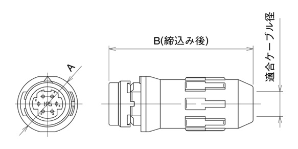
Plug
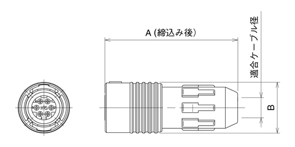
Dimensional drawing of solder type
| Product No. | HRS No. | A | B | Applicable cable diameter | Note | Weight | |||
|---|---|---|---|---|---|---|---|---|---|
| HR30-6P-3S(71) | 130-0004-1 71 | 29.8 | ø12.6 | ø4.2 to 5 | Solder pot inner diameter ø1.1 | 4 g | |||
| HR30-6P-6S(71) | 130-0010-4 71 | Solder pot inner diameter ø0.8 | |||||||
| HR30-6P-6P(71) | 130-0009-5 71 | 30.3 | |||||||
| HR30-6PA-3S(71) | 130-0021-0 71 | 29.8 | ø3.5 to 4.3 | Solder pot inner diameter ø1.1 | |||||
| HR30-6PA-6S(71) | 130-0019-9 71 | Solder pot inner diameter ø0.8 | |||||||
| HR30-6PA-6P(71) | 130-0020-8 71 | 30.3 | |||||||
| HR30-7P-12S(71) | 130-0027-7 71 | 39.8 | ø15.5 | ø6.2 to 7 | Solder pot inner diameter ø0.6 | 6.7 g | |||
| HR30-8P-12P(71) | 130-0026-4 71 | ||||||||
Table of dimensions

Dimensional drawing of crimp type
| Product No. | HRS No. | A | Applicable cable diameter | Note | Weight | |||
|---|---|---|---|---|---|---|---|---|
| HR30-7P-10SC(71) | 130-0013-2 71 | 39.8 | ø6.2 to 7 | Compatible crimp terminal HR30-SC-211 | 6 g | |||
| HR30-7P-12SC(71) | 130-0014-5 71 | |||||||
| HR30-8P-12PC(71) | 130-0015-8 71 | Compatible crimp terminal HR30-PC-211 | ||||||
Table of dimensions
Receptacle

Dimensional drawing of solder type
| Product No. | HRS No. | A | B | C | D | E | F | Note | Weight | |||
|---|---|---|---|---|---|---|---|---|---|---|---|---|
| HR30-6R-3P(71) | 130-1003-4 71 | 16 | 8.3 | ø12 | ø8.9 | M8 × 0.75 | 10 | Solder pot inner diameter ø1.1 | 2 g | |||
| HR30-6R-6P(71) | 130-1009-0 71 | Solder pot inner diameter ø0.8 | ||||||||||
| HR30-6R-6S(71) | 130-1008-8 71 | 18.4 | ||||||||||
| HR30-7R-12P(71) | 130-1016-6 71 | 18.6 | 9.3 | ø15 | ø11.5 | M11 × 1 | 13 | Solder pot inner diameter ø0.6 | 3.4 g | |||
| HR30-8R-12S(71) | 130-1018-1 71 | |||||||||||
Table of dimensions
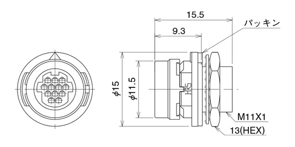
Table of dimensions for crimp type
| Product No. | HRS No. | Note | Weight | |||
|---|---|---|---|---|---|---|
| HR30-7R-10PC(71) | 130-1012-5 71 | Compatible crimp terminal HR30-PC-211 | 3 g | |||
| HR30-7R-12PC(71) | 130-1013-8 71 | |||||
| HR30-8R-12SC(71) | 130-1014-0 71 | Compatible crimp terminal HR30-SC-211 | ||||
Table of dimensions
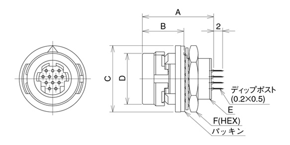
Dimensional drawing of DIP type
| Product No. | HRS No. | A | B | C | D | E | F | Weight | ||
|---|---|---|---|---|---|---|---|---|---|---|
| HR30-6R-6PD(71) | 130-1020-3 71 | 14.9 | 8.3 | ø12 | ø8.9 | M8 × 0.75 | 10 | 2 g | ||
| HR30-6R-6SD(71) | 130-1021-6 71 | 15.2 | ||||||||
| HR30-7R-12PD(71) | 130-1017-9 71 | 16 | 9.3 | ø15 | ø11.5 | M11 × 1 | 13 | 3.4 g | ||
| HR30-8R-12SD(71) | 130-1019-4 71 | |||||||||
Table of dimensions
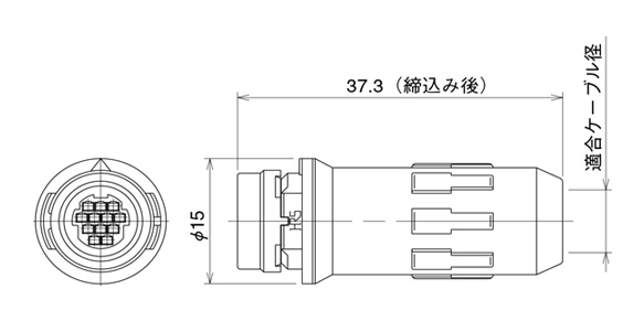
Jack
Dimensional drawing of solder type
| Product No. | HRS No. | A | B | Applicable cable diameter | Note | Weight | ||||||
|---|---|---|---|---|---|---|---|---|---|---|---|---|
| HR30-6J-6P(71) | 130-2009-6 71 | ø12 | 28.8 | ø4.2 to 5 | Solder pot inner diameter ø0.8 | 3 g | ||||||
| HR30-6JA-6P(71) | 130-2018-7 71 | ø3.5 to 4.3 | ||||||||||
| HR30-7J-12P(71) | 130-2020-9 71 | ø15 | 37.3 | ø6.2 to 7 | Solder pot inner diameter ø0.6 | 5.7 g | ||||||
| HR30-8J-12S(71) | 130-2019-0 71 | 5.9 g | ||||||||||
Table of dimensions
Dimensional drawing of crimp type
| Product No. | HRS No. | Applicable cable diameter | Note | Weight | ||||
|---|---|---|---|---|---|---|---|---|
| HR30-7J-10PC(71) | 130-2015-9 71 | ø6.2 to 7 | Compatible crimp terminal HR30-PC-211 | 5 g | ||||
| HR30-7J-12PC(71) | 130-2017-4 71 | |||||||
| HR30-8J-12SC(71) | 130-2016-1 71 | Compatible crimp terminal HR30-SC-211 | ||||||
Table of dimensions
Crimp contact
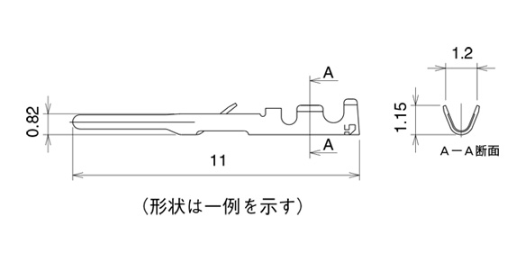
Table of dimensions for male terminals
| Type | Product No. | HRS No. | Weight | |||
|---|---|---|---|---|---|---|
| Loose contact | HR30-PC-111 | 130-0022-3 | 0.03 g / 1 pin | |||
| Reel contact | HR30-PC-211 | 130-0016-0 | 0.03 g / 1 pin | |||
Table of dimensions

Table of dimensions for female terminals
| Type | Product No. | HRS No. | Weight | |||
|---|---|---|---|---|---|---|
| Loose contact | HR30-SC-111 | 130-0023-6 | 0.03 g / 1 pin | |||
| Reel contact | HR30-SC-211 | 130-0017-3 | 0.03 g / 1 pin | |||
Table of dimensions
Product Usage
1. During mating
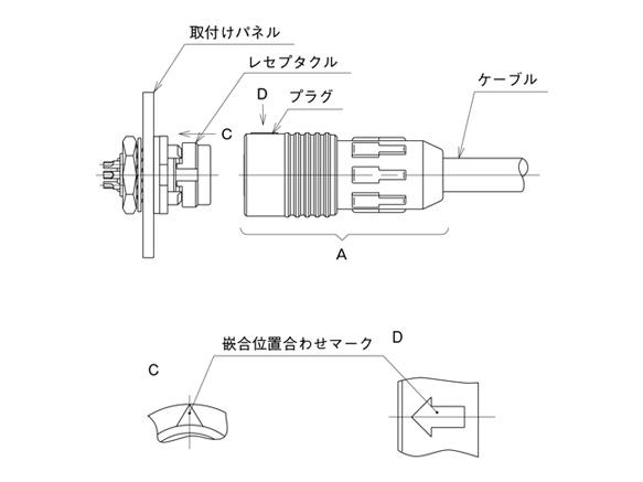
When mounting, smooth mating will be achieved by holding plug "A" and aligning the arrow markings of the plug with those of the receptacle, then pushing the plug straight in.
2. During un-mating
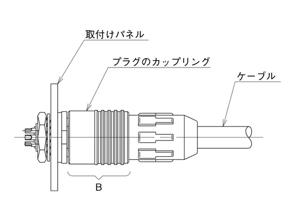
When removing the plug from its connected condition, hold the plug by the push/pull locking collar (coupling "B") and pull straight off.
Product Precautions
Precautions
- 1. Make sure the power is off before mating or un-mating the connector.
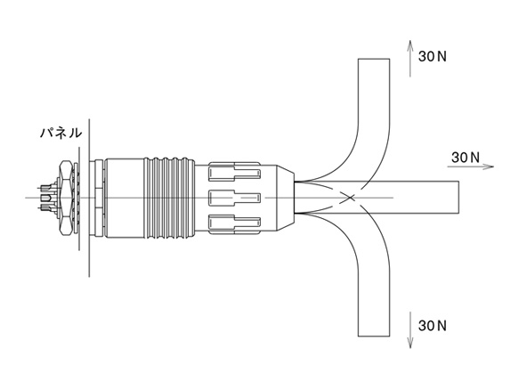
- 2. When mating the connector, push it on with a force of a least 30 N. After mating, pull lightly on the connector to check for proper mating and to ensure the connector is firmly locked to the receptacle.
- 3. After mating the connector, do not apply a force over 30 N to the cable in the directions shown by the arrows. An excessive load can lead to connector damage.
- 4. To maintain the waterproof performance, cable clamping force and cable rotational stability, please use a cable within the recommended range for cable diameters. Because the performance will differ depending on the cable structure, make sure to check all specifications of the cable assembly before use or production.
- 5. Please assemble and install the connector and components with the specified tightening torque. If the tightening torque is too weak or too strong, loosening or breakage can occur.
Precautions for using heat shrink tubing
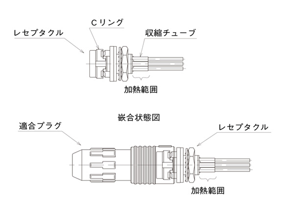
The manufacturer recommends that you use shrink tubing over the solder connections in order to protect the soldered wires and to enhance insulation. However, be careful when applying heat in this area when installing the shrink tube so that excess heat does not bleed into or affect the resin parts as shown in the figure below.
If the product does become heated beyond the area shown and into the resin parts, the following could occur.
- 1. Deformation of the C ring. This could result in prevention of locking during mating.
- 2. Melting of some parts.
To prevent the deformation of the C rings of the receptacles and the jack, the manufacturer recommends heat to be applied after mating with a compatible plug.