HR10 Series Miniature Circular Connector
Caution
Product Description
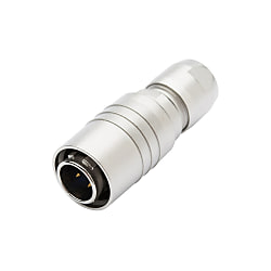
Small-diameter circular connectors, with the smallest size being close to the thickness of a cigarette. For use with camera interfaces.
[Features]
· Single-action, push-pull lock mechanism enables quick insertion and removal.
· Simply push when inserting to securely lock.
· Five key ensures insertion only to the intended location even when inserting by feel.
· Contacts are arranged in a safe configuration that prevents the contact pins from being damaged when aligning the five key by feel.
· Push-pull lock means little space is necessary for insertion and removal, making it possible to mount multiple connectors in close proximity to each other.
· No small screwdrivers are required for connector disassembly or assembly, meaning wiring and mounting can be performed easily using a JIS wrench.
· With a simple and neat external appearance and a satin finish on the top surface, the connectors will not stand out.
· Compact, high density, high reliability and simple design.
· Extremely simple insertion and removal.
[Applications]
· Convenient for a wide range of equipment due to its small size, light weight, and excellent operability.
High-Performance Circular Connector for Camera Interfaces
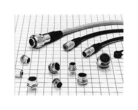
Can be used with a wide range of equipment thanks to its small size, light weight, and excellent operability.
Specifications of HR10 Series Miniature Circular Connectors
Product Standards
| Rating | Shell Size | Number of Contacts | Rated Current |
|---|---|---|---|
| 7 | 4 5 6 | 2 A | |
| 10 | 10 12 | 2 A | |
| 13 | 20 | 2 A |
| Rating | Shell Size | Number of Contacts | Rated voltage |
|---|---|---|---|
| 7 | 4 5 6 | 150 V AC, 200 V DC 100 V AC, 140 V DC 100 V AC, 140 V DC | |
| 10 | 10 12 | 100 V AC, 140 V DC | |
| 13 | 20 | 100 V AC, 140 V DC |
| Rating | Operating Temperature Range | -25 to 85°C |
|---|---|---|
| Storage temperature range | -10 to 60°C |
| Item | Standard | Conditions |
|---|---|---|
| 1. Contact resistance | 10 mΩ or less | Measure at 1 A DC |
| 2. Insulation resistance: | 1,000 MΩ or more | Measure at 100 V DC |
| 3. Withstand voltage | There shall be no flashover or dielectric breakdown | 300 V AC for 1 min., 4-pin: 500 V AC for 1 min. |
| 4. Vibration resistance | There shall be no electrical discontinuity for 10 μs or greater | Test at 10 to 55 Hz/cycle, Single amplitude: 0.75 mm Three directions, 2 hours each. |
| 5. Shock | There shall be no electrical discontinuity for 10 μs or greater | Test at acceleration 490 m/s2, duration: 11 ms, 3 directions, 3 times each. |
| 6. Mating cycle | Contact resistance 15 mΩ or less | 1,000 times |
| 7. Temperature cycle | Insulation resistance 1,000 MΩ or more | Leave at -55°C: 30 mins. > Room temperature: 10 to 15 mins. > 85°C: 30 mins.>Room temperature: 10 to 15 mins. Total of 5 cycles. |
| 8. Humidity resistance | Insulation resistance: 5 MΩ or more (at high humidity), 50 MΩ or more (when dry) | Temperature: 40°C, relative humidity: 90 to 95%, left for 96 hours. |
Materials/Processing
| Item | Materials | Finish | Notes |
|---|---|---|---|
| Exterior | Zinc alloy, brass | Matte-finished nickel plating | ― |
| Insulator | Polyamide resin, PBT resin | ― | Blue, black |
| Contacts | Copper alloy | HR10: gold plating HR10A: silver plating | ― |
| Product Name | Materials | Finish |
|---|---|---|
| Plug shell | Brass | Gold plating |
| Jack shell | Brass | |
| Insulator | Tetrafluoride resin | |
| Male contact | Phosphor bronze | Gold plating |
| Female contacts | Beryllium copper |
Coaxial Contact Materials/Processing
| Item | Standard Value |
|---|---|
| Impedance | 50 Ω |
| Insulation resistance | 1,000 MΩ or more at 250 V DC |
| Contact resistance | Center 6.5 mΩ or less, Exterior 4 mΩ or less at 1 A DC |
| Withstand Voltage | At 250 V AC (r.m.s) for 1 min. |
| Voltage standing wave ratio | 0 to 1,000 MHz, 1.3 or less |
| Pull force (extraction force) | 4.9 N (500 gf) or more |
Coaxial contact performance
Connector Combination Diagram
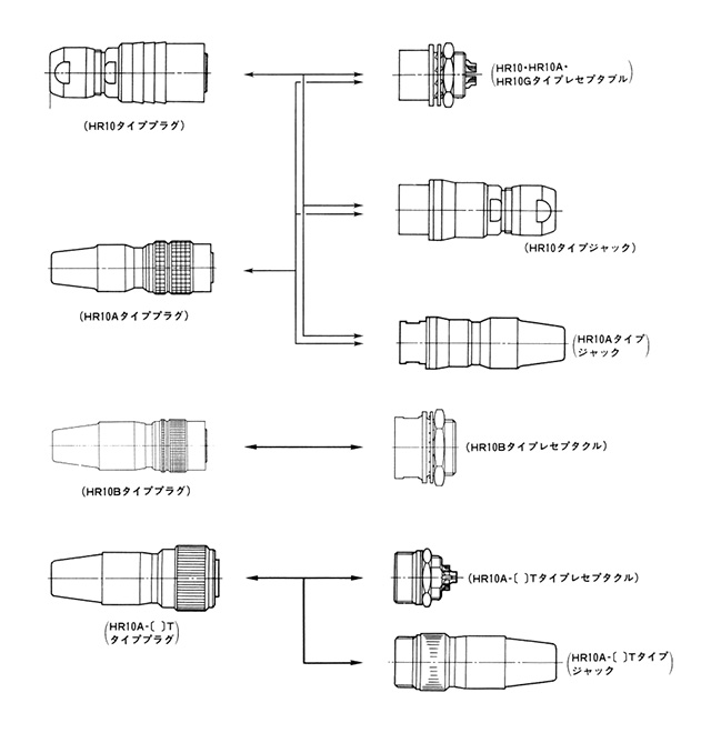
(Notes)
- 1. When using a plug with male terminal, be sure to use a receptacle or jack fitted with female terminal.
- 2. The standard finish of the terminal is gold plating for the HR10, and silver plating for the HR10A and HR10G. Be sure to use male and female connectors of the same plating.
Product Usage
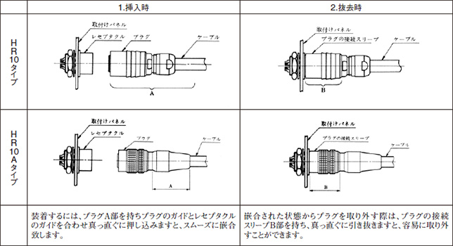
Connector Handling

Wiring procedure (plug side)
- *This applies also to the jack side assembly procedure.
- *No special procedure is given here for the receptacle side because no special procedure is necessary.
| HR10 Type | HR10A Type | |
|---|---|---|
| 1 | Use cables with a nominal sectional area of 0.129 mm2 (26 AWG) or less at the finished outer diameters applicable for each size. | |
| 2 | After processing the cable ends according to the dimensions in the above drawings, fit the parts to the cable as shown in the drawings. | |
| Fit the parts to the cable in the following order: tightener, clamp washer and plug body. | Fit the parts to the cable in the following order: tightener, cord bushing and plug body. | |
| 3 | (Solder type) Insert the P shell unit into the assembly tool stand and solder it. (Crimp type) After crimping the appropriate crimp terminal to the cable core, insert the crimp terminal into the terminal hole in the P shell unit. | |
| 4 | Assemble the connector in the following order. | |
| (1) Screw the plug body into the thread in the P shell unit with the tightening force shown in Table 1 using a torque wrench with a fixed torque. Before tightening the plug body, slacken part C so that no load is applied to the soldered wires. (2) Apply the clamp washer to the bifurcated part of the plug body, and then tighten the tightener until surface B touches the plug body surface A. (Note) In order to prevent loosening, apply a screw-locking adhesive at the threaded section. | (1) Fix by crimping the clamp accompanying the cable with the cable crimping tool (HR10A-TC-02). (2) Screw the plug body into the thread in the P shell unit with the tightening force shown in Table 1 using a torque wrench with a fixed torque. Before tightening the plug body, slacken part D so that no load is applied to the soldered wires. (3) Tighten the set screw so that the tip of the screw presses one of the 2 bosses on the clamp. Fix the set screw with a tightening torque of 0.3 N·m (3 kgf/cm.) (4) Attach the cord bushing to the plug body. (Note) In order to prevent loosening, apply a screw-locking adhesive at the threaded section. | |
| 5 | This completes the work. | |
Wiring procedure (plug side) work steps
Product Usage Precautions
- 1. Make sure the power is off before mating or un-mating the connector.
- 2. Use connectors with socket (female) contacts at the power side of the circuit.
- 3. Make sure that the coupling is in the completely locked position.
- 4. Cable clamping, cable rotation, and other forces may vary with the cable construction. Make sure that your cable is suitable for use with these connectors before usage and production.