Rectangular Miniature Multi-Pin Rack / Panel Crimp Connector, QR/P1 Series
Caution
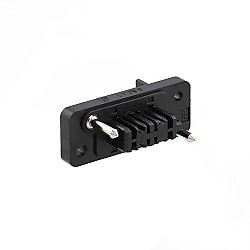
Product Description
A rectangular connector designed to be compact and for use in high-density mounting setups. The crimp terminals are separated into those for power supplies and those for signals.
[Features]
· The terminals have a smooth insertion/extraction feel and a stable contact pressure thanks to the point and blade contacts.
· Enables sufficient widths to be obtained in regards to variations in connector coupling lengths inherent with plug-in connections.
· For the terminal arrangement inside the housing, there are 2 opposing contacts on a single side for the 12- pole version and 2 opposing poles on both sides (total of 4 poles) for the 8- pole and 24-pole versions.
· With the 32-pole version, there are 3 opposing poles on a single side (total of 6 poles), creating a space between the other terminals. Also features creepage distance for sufficient resistance to high voltages.
· Insulation material uses flame-retardant material (UL94V-0).
· Metallic guide pin resistant to coupling shock.
· Mounting to panels or racks is performed by fixing with floating type bushing.
· Can be easily inserted and extracted.
· Plug-in for the connection structure, it has to have a room to enable fitting length.
· Features a floating bushing to enable a floating structure.
· This product has UL, CSA and TÜV certification.
[Applications]
· ·Convenient for power supply.
Small Rectangular Multi-Electrode Solderless Connector For Racks / Panels

QR/P1 Series
Specifications of QR/P1 Series Rack and Panel Connector
Product Standards
| QR/P1 Safety Standard Certification Ratings | |||||||
|---|---|---|---|---|---|---|---|
| Safety Standards | UL | CSA | TÜV | ||||
| Operating Temperature Range | -10 to +60°C | ||||||
| Rated voltage | Power Supply Unit | 120 V AC | 250 V AC | 125 V AC | 250 V AC | 250 V AC, 300 V DC | |
| Signal part | 125 V AC, 150 V DC | ||||||
| Rated Current | AWG#14 | 10 A | 3 A | 10 A | 3 A | 10 A | |
| AWG#16 | 8 A | ||||||
| AWG#18 | 3 A | 1 A | 3 A | 1 A | 5 A | ||
| AWG#20 | 2.5 A | ||||||
| AWG#22 | 1 A | ||||||
| AWG #24 | Power Supply Unit | 2 A | 1 A | 2 A | 1 A | ||
| Signal part | 1 A | 0.5 A | 1 A | 0.5 A | |||
| AWG#26 | 1 A | 0.5 A | 1 A | 0.5 A | |||
| AWG#28 | – | ||||||
Materials/Processing
| Part Name | Materials | Color/Finish |
|---|---|---|
| Insulator | PBT resin* | Black |
| Contacts | Phosphor bronze | Nickel base Selective gold plating |
- *UL94V-0
Power Supply Contact Configuration
Male housing (diagram viewed from wiring side), "■" indicates a contact hole for the power supply

QR/P1-8P/C(51)

QR/P1-12P-C(51)

QR/P1-16P-C(51)

QR/P1-24P-C(51)

QR/P1-32P-C(51)
Product Outline Drawing And Dimensions
Housing

Male housing

Dimensional drawing

Female housing

Dimensional drawing
Contact

Male contact for power supply
Plating: nickel base and selective gold plating

Female contact for power supply
Plating: nickel base and selective gold plating

Male contact for signal
Plating: nickel base and selective gold plating

Female contact for signal
Plating: nickel base and selective gold plating
Panel mounting dimensional drawing (for S insulated case)

Mounting from rear of panel

Mounting from front of panel
Units: mm, Tolerance: ±0.2
| Symbol | 8-contacts | 12-contacts | 16-contacts | 24-contacts | 32-contacts | |
|---|---|---|---|---|---|---|
| Rear surface mounting | A | 36.9 | 42 | 48.1 | 59.3 | 76 |
| B | 29.4 | 34.5 | 40.6 | 51.8 | 68.5 | |
| C | 28.4 | 33.5 | 39.6 | 50.8 | 67.5 | |
| D | 4.3 | 3.3 | 4.3 | 4.3 | 4.3 | |
| Front surface mounting | E | 22.4 | 27.5 | 33.6 | 44.8 | 61 |
| F | 36.9 | 42 | 48.1 | 59.3 | 76 | |
| G | 4.3 | 3.3 | 4.3 | 4.3 | 4.3 | |
- *The panel mounting dimensions for the P insulation case are a mirror image of the mounting dimensions for the S insulated case in which the right and left sides are reversed.