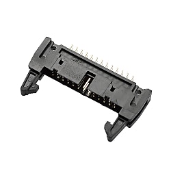
HIF3B Series MIL Standard-Compliant Ribbon Cable Connector
Caution
Product Description
MIL standard-compliant rectangular ribbon cable connector.
[Features]
· HIF3B series products are developed to comply with the MIL standard and can be used in a wide range of applications.
· Compatible with HIF3 series.
· HIF3B series products are UL-listed connectors.
· Features a mechanism to prevent mis-insertion.
· A form in which inserting the guide key (polarity key) on the pin header side creates a convex section that fits into the concave section (polarity keyway) of the socket. (MIL standard)
· A form in which the mis-insertion prevention guide (polarity guide) on the socket side fits into the slot (polarity slot) on the pin header side.
· A system that embeds the polarizing key in the socket hole and guides it.
· A guide system in which the convex section on the socket side (HIF3A type) combines with the slot located in the center of the pin header side.
· The compatible wire (UL2651) is an AWG#28 ribbon cable (7-core/0.127 mm, jacket diameter of 0.9 ± 0.2 mm).
[Applications]
· A wide variety of models are available, enabling use with a wide range of equipment.
MIL Standard-Compliant Product

HIF3B Series list
Specifications of HIF3B Series MIL Standard Compliant Ribbon Cable Connector
Product Standards
| Rating | Rated current - ID: 1 A, Crimping: 1 A (AWG32/36), Other: 3 A | Rated voltage: 200 V AC |
|---|---|---|
| Operating temperature range: -55°C to 85°C (Note 1) | Operating humidity range: 40% to 80% | |
| Storage temperature range: -10°C to 60°C (Note 2) | Storage humidity range: 40% to 70% (Note 2) |
| Item | Standard | Conditions |
|---|---|---|
| 1. Insulation resistance | 1,000 MΩ or more | Measure at 500 V DC |
| 2. Withstand voltage | There shall be no flashover or dielectric breakdown | Energize at 650 V AC rms for 1 min. |
| 3. Contact resistance | 15 mΩ or less | Measure at 0.1 A |
| 4. Vibration resistance | There shall be no electrical discontinuity for 1 μs or greater | Frequency: 10 to 55 Hz, Single amplitude: 0.75 mm, Three axial directions, 2 hours each |
| 5. Humidity resistance | Insulation resistance: 1,000 MΩ or more | Temperature: 40°C ±2°C, relative humidity: 90 to 95%, left for 96 hours |
| 6. Temperature cycle | There shall be no cracking or abnormalities with any of the parts | (-55°C: 30 mins. > 15 to 35°C: Max. 5 mins. > 125°C: 30 mins. > 15 to 35°C: Max. 5 mins.) 5 cycles |
| 7. Durability (Mating / Un-mating) | Contact resistance: 15 mΩ or less | 500 mating / un-mating cycles |
| 8. Solder heat resistance | No melting of resin parts affecting performance | Solder bath: 260°C for 10 seconds Manual soldering: Soldering iron temperature of 360°C for 5 seconds |
(Note 1) This includes temperature increases caused by the flow of current.
(Note 2) The term "storage" refers to products stored for long periods of time prior to mounting and use. The operating temperature range and humidity range covers non-conducting condition of installed connectors in storage, shipment or during transportation.
(Note 3) Be aware that deformation may occur to the pin header type lock if an excessive load is placed on the inside of the lock.
Materials/Processing
| Part Name | Materials | Finish | Note |
|---|---|---|---|
| Insulator case | PBT | Black | UL94V-0 |
| Lock | |||
| Contacts | Brass | Contact area: 0.2 μm min. gold plating | - |
| DIP area: 2 μm min. pure tin plating | - |
Four wall right-angle through hole (HIF3B*-**PA-2.54DS), Four wall straight type (HIF3B*-**PA-2.54DSA), Four wall straight through hole, flux-blister prevention type (HIF3C*-**PA-2.54DSA), Three wall right-angle through hole (HIF3B-**PA-2.54DS), Three wall straight through hole (HIF3B-**PA-2.54DSA)
*Models with plating are a (71) specification.
| Part Name | Materials | Finish | Note |
|---|---|---|---|
| Insulator case | PBT | Black | UL94V-0 |
| Lock | |||
| Contacts | Brass | Surface: 0.2 μm min. gold plating | - |
Wrapping type (HIF3B*-**P-2.54W), Double-layer right-angle through hole (HIF3B*-**PA-2.54WB)
*Models with plating are a (71) specification.
| Part Name | Materials | Finish | Note |
|---|---|---|---|
| Insulator | PBT | Black | UL94V-0 |
| ID contact | Beryllium copper | Contact area: 0.2 μm min. gold plating | - |
| ID area: 0.03 μm min. gold plating | - |
Socket type (for ID type, with mis-insertion prevention guide / HIF3B*-**D-2.54R), Socket type (for ID / HIF3B-**D-2.54R)
| Part Name | Materials | Finish | Note |
|---|---|---|---|
| Insulator | PBT | Black | UL94V-0 |
Socket type (for crimping / HIF3B*-**D-2.54C)
HIF3 Series Mating Combination Diagram

Board-to-cable type

Board-to-board type
Product Usage
Socket Side (Crimping) Assembly Method
Crimping method
Dedicated tools compatible with each terminal are necessary for connecting crimped contacts.
Contact insertion method
After confirming the crimping contact orientation, insert all the way to the back of the insulation case.
After inserting, lightly pull on the cable to confirm whether the contact lance is firmly fixed into the insulation case.

Contact insertion method

Contact replacement method
Contact replacement method
Use a contact extraction tool to remove any incorrectly inserted contacts.