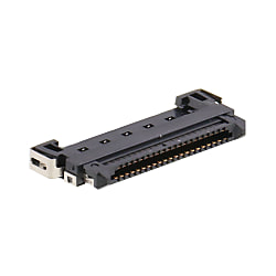
1‑mm Pitch Board-To-Cable Connector For LVDS Signals, FX15 Series
Caution
Product Description
A shielded rectangular connector with support for LVDS transmissions.
[Features]
· Board-side connectors are shared, while discrete cables, micro coaxial cables and shielded FFC cables can be selected depending on the given application.
· A small, space-saving structure with double-row contacts and single-row leads.
· Space-saving, with transmission channels of equal length.
· A large number of variations. Superior mating performance thanks to its large guide shape.
· Superior side lock operation.
·High shielding effects (FX15S Series.)
[Applications]
· Useful for various types of wiring work.
LVDS Signal Compatible Shielded Connector With Shared Board Side Connector and Selectable Cable Side

Discrete cable and small-gauge coaxial cable can be selected
Main Features of FX15 Series 1‑mm Pitch Board-To-Cable Connector For LVDS Signals

The double-row contact and single-row lead design help save on space and ensure equal length transmission lines
Mounting section: 0.5‑mm pitch single-row structure
Contact section: 1‑mm pitch staggered double-row structure
Contacts consolidated into 1 row for equal length transmission lines

Good mating performance thanks to the large guide shape
Large guide post

Superior side lock operation
Type with metal shields (FX15, FX15S Series)

Type without metal shield (FX15M Series)

High shielding effects
Product Standards
| Rating | Rated current Rated voltage | 0.5 A 100 V AC | Operating temperature range Storage temperature range | -55 to 80°C (Note 1) -10 to 60°C (Note 2) |
|---|
| Item | Standard | Conditions |
|---|---|---|
| 1. Contact resistance | 60 mΩ or less (Note 3) | Measure at 1 mA |
| 2. Insulation resistance | 500 MΩ or more | Measure at 100 V DC |
| 3. Withstand voltage | There shall be no flashover or dielectric breakdown | Energize at 300 V AC for 1 min. |
| 4. Total mating / un-mating force | Insertion force: 30 N or less Extraction force: 2 N or more | Measure using a compatible connector |
| 5. Durability (Mating / Un-mating) | Contact resistance: 80 mΩ or less (Note 3) | 50 mating / un-mating cycles |
| 6. Vibration Resistance | There shall be no electrical discontinuity for 1 μs or greater | Frequency: 10 to 55 Hz, Single amplitude: 0.75 mm, Three axial directions, 2 hours each |
| 7. Shock Resistance | There shall be no electrical discontinuity for 1 μs or greater | Acceleration: 490 m/s2, Duration: 11 ms, Half sine wave, Three times each in 3 axial directions |
| 8. Humidity resistance | Contact resistance: 80 mΩ or less (Note 3) No damage, cracks, or parts dislocation | Temperature: 40°C, relative humidity: 90 to 95%, left for 96 hours |
| 9. Temperature Cycle | Contact resistance: 80 mΩ or less (Note 3) Insulation resistance: 500 MΩ or more | Test in 5 cycles at temperatures of -55 > 15 to 35 > 85 > 15 to 35°C and at times of 30 mins. > 5 mins. > 30 mins. > 5 mins. |
| 10. Salt Spray | Contact resistance: 80 mΩ or less (Note 3) No corrosion (which can lead to losses in functionality.) | Leave for 48 hours with 5% concentrate salt water |
(Note 1) This includes temperature increases caused by the flow of current.
(Note 2) The term "storage" refers to products stored for long periods of time prior to mounting and use.
(Note 3) Includes the conductor resistance of the connected wire (L = 12 mm)
Product Materials/Processing
Receptacle
| Part Name | Materials | Finish | Standard |
|---|---|---|---|
| Insulator | Polyamide resin | Black | UL94V-0 |
| Contacts | Copper alloy | Contacts: gold plating Mounting section: pure tin plating | - |
| Metal shell (only type with shield) | FX15S: Nickel silver FX15SC: stainless steel | FX15S: - FX15SC: pure tin plating | - |
| Metal fittings (only type with shield) | Copper alloy | Selective gold flash plating | - |
Plug
| Part Name | Materials | Finish | Standard |
|---|---|---|---|
| Insulator | Polyamide resin | Black | UL94V-0 |
| Contacts | Copper alloy | Contacts: gold plating Wire connection: pure tin plating | - |
| Metal shell (only type with shield) | Nickel silver | - | - |
| Metal latch locks (only type with shield) | Stainless steel | - | - |
| Metal shell / integrated latch lock (micro coaxial cable type) | Stainless steel | Nickel plating | - |
Recommended Temperature Profile For This Product

The temperature profile is based on the following conditions. This may vary depending on conditions so be sure to check before implementing.
Applicable conditions
Test board - Dimensions: 40 × 30 × 1 (mm)
Reflow type - Material: glass epoxy
Solder composition: Sn-3 Ag-0.5 Cu (flux content: 10.5 wt%)
Metal mask thickness: 0.12 mm
(Note 1) This temperature profile is a recommended value.
(Note 2) The reflow process shall be performed two times or less.
(Note 3) The temperature profile may vary due to external conditions such as the type of cream solder, manufacturer, and board size as well as other material factors. Be sure to check all potential factors before use.
Cleaning Conditions
Organic solvent cleaning
| Solvent | Room Temperature Cleaning | Heated Cleaning |
|---|---|---|
| IPA (Isopropyl Alcohol) | ○ | ○ |
Water-based cleaning
When using water type cleaning agents (e.g., terpene, alkali saponifiers), select the cleaning agent based on the documentation issued by the various manufacturers of cleaning agents which describes the effects on metals and resins.
Be careful that parts are not left with moisture remaining on them.
Precautions for cleaning
Residual flux or cleaning agent on the connectors when washing with organic solvents or water type cleaners can give rise to the deterioration of electrical performance. In this regard it is important to check whether a thorough washing has been performed.