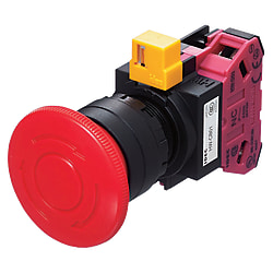
ø22 HW Series Pushbutton Emergency Stop Switches
Caution
Product Description
ø22 HW Series Emergency Stop Switches (Non-Illuminated)
ø22 HW Series Pushbutton Emergency Stop Switches by IDEC a reliable solution designed for maximum safety in industrial environments.
[Features]
● Mounting Hole Diameter :22 mm
● Contact Configuration : 1a, 1b,2a, 2b, 3a, 3b and 4b
● Push button operation : Push to lock/turn to reset, Push-pull and Push to lock, reset with key
[Application]
These switches are engineered to provide immediate cessation of machine operations in emergency situations.
Specification Change Notice of IDEC Emergency Stop Switches / Safety Switches
Affected products: φ22 HW series screw-type control unit
φ22 HW series push-in type control unit (finished product, operation unit)
Changes: (1) Change in shape of connection unit, (2) Change in model number of connection unit
Implementation period: From November 2022 onwards, there is a possibility that old and new products will be shipped together. Please note.
Details:
Model Emergency Stop Switches / Safety Switches | Products starting with the following model numbers | (1) Change in the shape of the control unit |
|---|---|---|
Push button switch | HW□B-M1 | can be |
Push button switch | HW□B-A1 | none |
Push button switch | HW□B-※3 | none |
Push button switch | HW□B-※4 | none |
Push button switch | HW□B-M5 | none |
Illuminated push button switch | HW□L-※1 | none |
Illuminated push button switch | HW□L-※4 | none |
2-point push button switch | HW7D-B HW7D-L | none |
Selector switch | HW1S-□T | can be |
Selector switch | HW1S-□L | can be |
Illuminated selector switch | HW1F-□ | none |
Illuminated selector switch | HW1F-□L | none |
Key selector switch | HW1K | can be |
Selector Push Button Switch | HW1R | none |
Mono Lever Switch | HW1M | none |
Emergency stop push button switch | HW1B-V3 | none |
Emergency stop push button switch | HW1B-V4,V5 | none |
Emergency stop push button switches | HW1B-X HW1B-Y | none |
*Model number designation code (M: momentary, A: alternate)
(1) Screw type: Change in shape of connection unit
The shape of the connection unit will be changed as follows.
The shape change allows the connection unit to be installed with one touch (the yellow lever stopper will no longer be necessary).
Emergency Stop Switches / Safety Switches, In accordance with the change in shape of the connection unit, the installation method described in the emergency stop push button switch instruction manual will be changed, and German and French will also be added.
Before change | After change |
|---|---|
|
|


(2) Screw type: Change in model number of connection unit
Due to the change in the shape of the connection unit, the model number on the side label will be changed to the product model number as follows.
Before change | After change |
|---|---|
Model number: HW-CB** | Display model number: Product model number display |
|
|


Specification Table of IDEC Emergency Stop Switches / Safety Switches
Contact Rating of Emergency Stop Switches / Safety Switches
| Contact Block | Rated Insulation Voltage | Emergency Stop Switches / Safety Switches 600V |
|---|---|---|
| Rated current | 10A | |
| Contact ratings based on load type JIS C8201-5-1, IEC60947-5-1 | AC-15 (A600) DC-13 |
Performance of Emergency Stop Switches / Safety Switches
Voltage and current used based on load type
| Operating voltage of Emergency Stop Switches / Safety Switches | 24V | 48V | 50V | 110V | 220V | 440V | ||
|---|---|---|---|---|---|---|---|---|
| Current used | AC 50/60Hz | AC-12 Resistive loads and semiconductor loads, etc. | 10A | - | 10A | 10A | 6A | 2A |
| AC-15 Control of AC electromagnetic load (>72VA) etc. | 10A | - | 7A | 5A | 3A | 1A | ||
| Direct current | DC-12 Resistive loads and semiconductor loads, etc. | 8A | 4A | - | 2.2A | 1.1A | - | |
| DC-13 DC electromagnet control, etc. | 4A | 2A | - | 1.1A | 0.6A | - | ||
Specification of Emergency Stop Switches / Safety Switches
| Standard use condition | Ambient temperature | >-25 to +60°C (but do not freeze) -40 to +80°C (but do not freeze) 45 to 85% RH (but do not freeze) |
|---|---|---|
| Storage ambient temperature | ||
| Ambient humidity | ||
| Minimum direct opening force | 50N | |
| Minimum operating distance until direct opening operation | 5.5mm | |
| Maximum Operating Distance | 10.0mm | |
| Contact Resistance | 50mΩ or less (initial value) | |
| Insulation resistance | 100MΩ or more (DC500V megger) | |
| Withstand voltage | Between live and non-live parts: AC2500V for 1 minute Between different terminals: AC2500V for 1 minute Between same terminals: AC2500V for 1 minute | |
| Shock Resistant | Malfunction: 100m/s2or less Endurance: 1000m/s2or less | |
| Vibration resistance | Malfunction: 5 to 55Hz Single amplitude 0.5mm Endurance: 30Hz Single amplitude 1.5mm | |
| Opening and closing frequency | 900 times/hour | |
| Durability | Mechanical: 500,000 times or more (push-pull switch: 250,000 times or more) Electrical: 500,000 times or more (push-pull switch: 250,000 times or more) (Note) Opening and closing at a switching frequency of 900 times/hour and a usage rate of 40%. | |
| Protective structure of Emergency Stop Switches / Safety Switches | IP65 (IEC 60529) | |
| Short circuit protection device | 250V/10A fuse (Type aM IEC60269-1/IEC60269-2) | |
| Terminal Shape | M3.5 screw | |
| Emergency Stop Switches / Safety Switches Weight (approx.) | 76g (HW1B-V322 type) 99g (HW1B-X422R type) 54g (HW1B-Y202 type) 79g (HW1B-V422R-EMO type) | |
Emergency Stop Switches / Safety Switches LED Bulb Equivalent Circuit
| Emergency Stop Switches / Safety Switches Equivalent Circuit |  |
|---|
Stop Switches Catalog Click here
Contact Rating
| Contact Block | Rated Insulation Voltage | 600V |
|---|---|---|
| Rated current | 10A | |
Contact ratings based on load type JIS C8201-5-1, IEC60947-5-1 | AC-15 (A600) DC-13 |
Performance
Voltage and current used based on load type
| Operating voltage | 24V | 48V | 50V | 110V | 220V | 440V | ||
|---|---|---|---|---|---|---|---|---|
Current used | AC 50/60Hz | AC-12 Resistive loads and semiconductor loads, etc. | 10A | - | 10A | 10A | 6A | 2A |
AC-15 Control of AC electromagnetic load (>72VA) etc. | 10A | - | 7A | 5A | 3A | 1A | ||
| Direct current | DC-12 Resistive loads and semiconductor loads, etc. | 8A | 4A | - | 2.2A | 1.1A | - | |
DC-13 DC electromagnet control, etc. | 4A | 2A | - | 1.1A | 0.6A | - | ||
Product Specifications
| Standard use condition | Ambient temperature | >-25 to +60°C (but do not freeze) -40 to +80°C (but do not freeze) 45 to 85% RH (but do not freeze) |
|---|---|---|
| Storage ambient temperature | ||
| Ambient humidity | ||
| Minimum direct opening force | 50N | |
| Minimum operating distance until direct opening operation | 5.5mm | |
| Maximum Operating Distance | 10.0mm | |
| Contact Resistance | 50mΩ or less (initial value) | |
| Insulation resistance | 100MΩ or more (DC500V megger) | |
| Withstand voltage | Between live and non-live parts: AC2500V for 1 minute Between different terminals: AC2500V for 1 minute Between same terminals: AC2500V for 1 minute | |
| Shock Resistant | Malfunction: 100m/s2 or less Endurance: 1000m/s2 or less | |
| Vibration resistance | Malfunction: 5 to 55Hz Single amplitude 0.5mm Endurance: 30Hz Single amplitude 1.5mm | |
| Opening and closing frequency | 900 times/hour | |
| durability | Mechanical: 500,000 times or more (push-pull switch: 250,000 times or more) Electrical: 500,000 times or more (push-pull switch: 250,000 times or more) (Note) Opening and closing at a switching frequency of 900 times/hour and a usage rate of 40%. | |
| Protective structure | IP65 (IEC 60529) | |
| Short circuit protection device | 250V/10A fuse (Type aM IEC60269-1/IEC60269-2) | |
| Terminal Shape | M3.5 screw | |
| Weight (approx.) | 76g (HW1B-V322 type) 99g (HW1B-X422R type) 54g (HW1B-Y202 type) 79g (HW1B-V422R-EMO type) | |
LED bulb equivalent circuit
| Equivalent circuit |  |
|---|