Push on Pin Terminal - PC/PCE Type

Brand :
NICHIFU
Caution
- The product images are representative images. Specifications, including shape and color, may vary for each model number.
- 【Insulation color change】
The following products will be switched to new specifications as soon as they are out of stock. (As of May 2021)
PC4009-M/F, PCE4009-M/F: Red → transparent red
PC4020-M/F, PCE4020/5020-M/F: Blue → transparent blue - 【Recommended replacements】
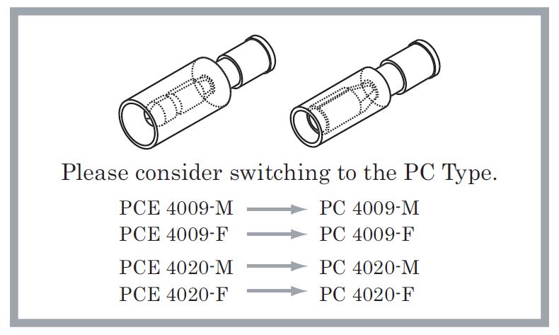
PCE Type will be replaced by PC Type. Please check the differences in specifications.
PCE 5020-M and PCE 5020-F, there are no alternate products
Product Description
· Exposed pin terminal PCE type crimp terminal.
[Features]
· Flame resistance.
· Operating temperature range: -40 ℃ to + 105 ℃.
[Application]
· Removable and ideal for use in relay connections.
Discontinued production of Bullets & Receptacles PCE Type

Plug-in pin terminal (PC/PCE type)
Material
- Terminal: Brass (electrolytic tin plating)
- Sleeve: Oxygen-free copper tube (electrolytic tin plating)
- Insulation: Nylon
Rated voltage
- 300V
Rated Current
Unit A
| Wire size (mm2) | 0.5 | 0.75 | 1.25 | 2 |
|---|---|---|---|---|
| Current A | 10 | 12 | 15 | 20 |
Operating temperature range
- -40℃~+105℃
Flame retardant
- UL94V-2
Applicable wire
- Each specification of the crimp terminal has been confirmed with JIS standard electric wire (IV, KIV, VSF).
Pin terminal built-in PC type

M type, F type

M type: Outline drawing

F type: Outline drawing
| Model number | Dimensions of each part (mm) | Wire Containment Range | Application Tools | Insulation | Standard Color | ||||||||
|---|---|---|---|---|---|---|---|---|---|---|---|---|---|
| Hand Tools | |||||||||||||
| φb | φB | φd | φD | L | F | H | Stranded wire mm2 | AWG | Main unit Head | ||||
| PC 2005-M | 2.0 | 5.1 | 1.7 | 3.1 | 26.5 | 15.0 | 11.5 | 0.5 - 0.75 | 20-18 | NH5 NH32 NH60 | nylon | Transparent | |
| PC 2005-F | 2.0 | 4.7 | 24.5 | 13.0 | NA 10 NA 3 | N10 10 N3 5 | |||||||
| PC 4009-M | 4.0 | 7.4 | 1.8 | 3.2 | 27.7 | 16.5 | 11.2 | 0.75–1.25 | 18-16 | NH11 NH32 | Red Transparent | ||
| PC 4009-F | 3.95 | 6.9 | 26.2 | 15.0 | NA 10 NA 3 | N10 11 N3 11 | |||||||
| PC-4020-M | 4.0 | 7.4 | 2.4 | 3.9 | 27.7 | 16.5 | 2.0 | 14 | NH12 NH32 | Blue transparent | |||
| PC-4020-F | 3.95 | 6.9 | 26.2 | 15.0 | NA 10 NA 3 | N10 12 N3 12 | |||||||
*PC 2005 does not have a molded part lock.
Pin terminal built-in PCE type
Color variations

M type, F type

M type: Outline drawing

F type: Outline drawing
| Model number | Dimensions of each part (mm) | Wire Containment Range | Application Tools | Insulation | Standard Color | ||||||||
|---|---|---|---|---|---|---|---|---|---|---|---|---|---|
| Hand Tools | |||||||||||||
| φb | φB | φd | φD | L | F | H | Stranded wire mm2 | AWG | Main unit Head | ||||
| PCE 4009-M | 4.0 | - | 1.8 | 3.2 | 25.2 | 13.0 | 12.2 | 0.75 ~ 1.25 | 18-16 | NH 11 NH 32 | nylon | Red Transparent | |
| PCE 4009-F | 3.95 | 6.5 | 31.5 | 20.3 | 11.2 | NA 10 NA 3 | N10 11 N3 11 | ||||||
| PCE 4020-M | 4.0 | - | 2.4 | 3.9 | 25.2 | 13.0 | 12.2 | 2.0 | 14 | NH 12 NH 32 | Blue Transparent | ||
| PCE 4020-F | 3.95 | 6.5 | 31.5 | 20.3 | 11.2 | ||||||||
| PCE 5020-M | 5.0 | - | 2.4 | 3.9 | 25.2 | 13.0 | 12.2 | NA 10 NA 3 | N10 12 N3 12 | ||||
| PCE 5020-F | 4.95 | 7.4 | 31.5 | 20.3 | 11.2 | ||||||||
Crimping position for application tool "NH 32"
