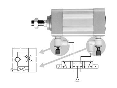
Speed Controller With Residual Pressure Release Valve, With Single-Action Fitting, AS□□□□FE Series

Caution
- For specifications and details, please refer to the catalog.
- Product images may be representative images. Refer to the catalog for details.
Product Description
[Features]
· A speed controller integrated with a residual pressure release valve.
· Releases residual pressure with the push of a button.
· The pressure-release button is in clearly visible red.
Speed Controller With Residual Pressure Release Valve, With One-Touch Fitting, AS□□□□FE Series Specifications
Releases residual pressure easily with the push of a button
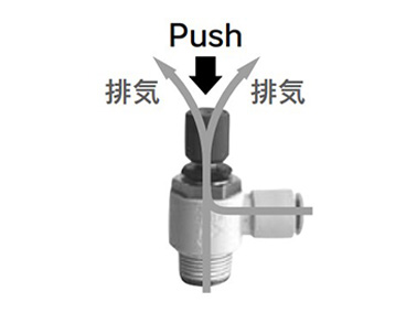
Exhaust image
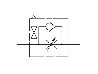
AS□□□□FE Series JIS symbol
Flow Rate and Sonic Conductance
| Model | AS22□1FE-01 AS23□1FE-01 | AS22□1FE-02 AS23□1FE-02 | ||||
|---|---|---|---|---|---|---|
| Tube outer diameter | Metric Size | øø4 (diameter 4 mm) | øø6 (diameter 6 mm) øø8 (diameter 8 mm) øø10 (diameter 10 mm) | øø4 (diameter 4 mm) | øø6 (diameter 6 mm) | øø8 (diameter 8 mm) øø10 (diameter 10 mm) |
| Controlled flow Free flow | Flow rate L/min (ANR) | 180 | 230 | 260 | 390 | 460 |
| Sonic conductance dm3/(s·bar) | 0.5 | 0.64 | 0.72 | 1.1 | 1.3 | |
| Critical pressure ratio | Controlled flow | 0.25 | 0.3 | |||
| Free flow | 0.2 | 0.3 | ||||
| Model | AS32□1FE AS33□1FE | AS42□1FE AS43□1FE | ||||
|---|---|---|---|---|---|---|
| Tube outer diameter | Metric Size | øø6 (diameter 6 mm) | øø8 (diameter 8 mm) | øø10 (diameter 10 mm) ø12 (diameter 12 mm) | øø10 (diameter 10 mm) | ø12 (diameter 12 mm) |
| Controlled flow Free flow | Flow rate L/min (ANR) | 660 | 790 | 920 | 1,580 | 1,710 |
| Sonic conductance dm3/(s·bar) | 1.8 | 2.2 | 2.6 | 4.4 | 4.8 | |
| Critical pressure ratio | Controlled flow | 0.25 | 0.25 | |||
| Free flow | 0.2 | 0.3 | ||||
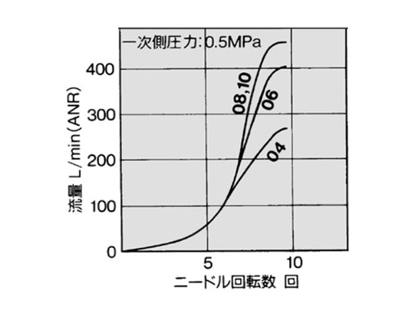
*Flow rate values are measured at a pressure of 0.5 MPa and a temperature of 20°C.
Needle Valve: Flow Rate Characteristics
- *The flow rate characteristics are representative values.
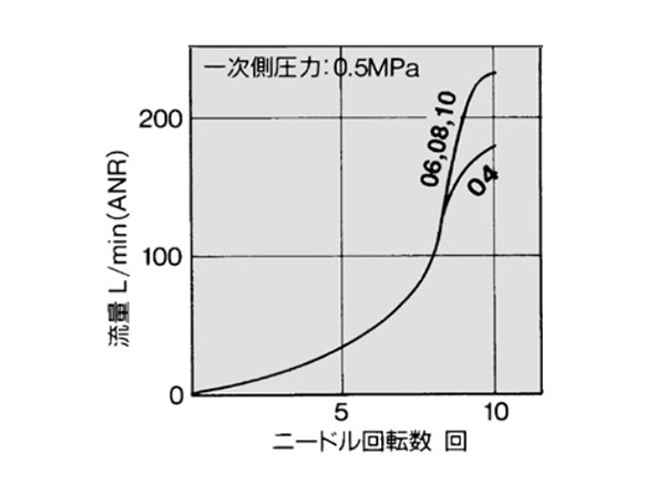
AS2201FE-01 / AS2211FE-01 / AS2301FE-01 / AS2311FE-01 flow rate characteristics graph
AS2201FE-02 / AS2211FE-02 / AS2301FE-02 / AS2311FE-02 flow rate characteristics graph
Structure drawing
Elbow Type
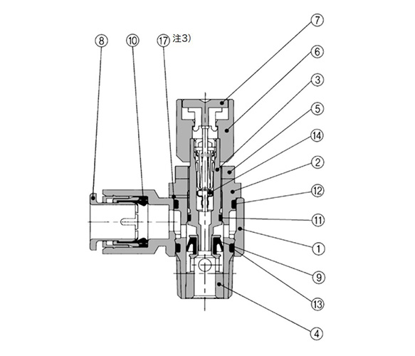
Meter-out type structure drawing
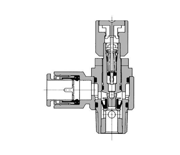
Meter-in type structure drawing
Universal Type
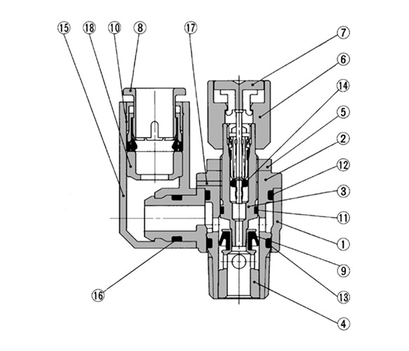
Meter-out type structure drawing
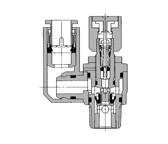
Meter-in type structure drawing
| Number | Part name | Material | Note |
|---|---|---|---|
| 1 | Body A | PBT | White |
| 2 | Body B | Brass | Electroless nickel plated |
| 3 | Needle | Brass | Electroless nickel plated |
| 4 | Seat ring | Brass | *1 |
| 5 | Lock nut | Steel*2 | - |
| 6 | Handle | Aluminum Alloy | Red painted |
| 7 | Push button | POM | Red |
| 8 | Cassette | - | - |
| 9 | U seal | HNBR | - |
| 10 | Seal | NBR | - |
| 11 | O-ring | NBR | - |
| 12 | O-ring | NBR | - |
| 13 | O-ring | NBR | - |
| 14 | Valve core | - | - |
| 15 | Elbow body | PBT | - |
| 16 | O-ring | NBR | - |
| 17 | Retaining pin | Stainless steel | *3AS2□□1FE-01 type only |
| 18 | Spacer | - | - |
*1: AS2□□1FE type is electroless nickel plated.
*2: AS2201FE-01 type is electroless nickel plated brass.
*3: AS2□□1FE-01 type only.
Drawings
Elbow Type
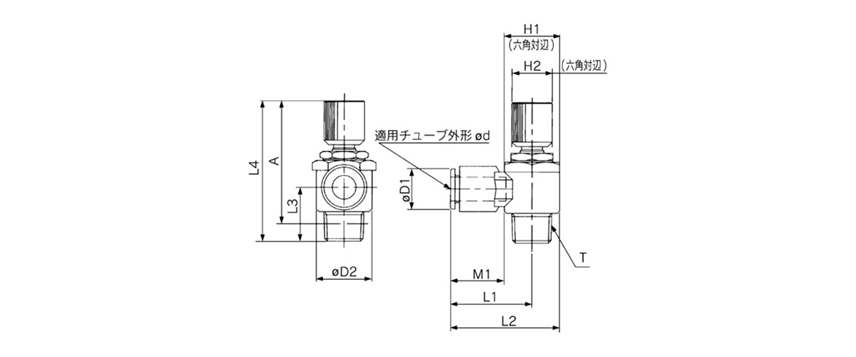
Elbow type dimensional drawing
(Units: mm)
| Model | Pipe Outer Diameter d | T | H1 | H2 | D1 | D2 | L1 | L2 | L3 | *1: L4 | *2: A | M1 | Weight g | ||
|---|---|---|---|---|---|---|---|---|---|---|---|---|---|---|---|
| Max. | MIN. | Max. | MIN. | ||||||||||||
| AS22□1FE-01-04SK | 4 | R 1/8 | 12 | 12 | 9.3 | 14.2 | 20.4 | 27.5 | 13.4 | 53 | 48 | 49.9 | 44.9 | 12.7 | 26 |
| AS22□1FE-01-06SK | 6 | 11.6 | 20.4 | 27.5 | 13.5 | 27 | |||||||||
| AS22□1FE-01-08SK | 8 | 15.2 | 25.3 | 32.4 | 18.5 | 29 | |||||||||
| AS22□1FE-01-10SK | 10 | 18.5 | 33.1 | 40.2 | 14.1 | 21 | 31 | ||||||||
| AS22□1FE-02-04SK | 4 | R 1/4 | 17 | 14 | 10.4 | 18.5 | 25.2 | 34.4 | 17.7 | 51.7 | 46.7 | 46.2 | 41.2 | 16 | 36 |
| AS22□1FE-02-06SK | 6 | 12.8 | 25.2 | 34.4 | 17 | 37 | |||||||||
| AS22□1FE-02-08SK | 8 | 15.2 | 27.2 | 36.4 | 18.5 | 39 | |||||||||
| AS22□1FE-02-10SK | 10 | 18.5 | 35.3 | 44.5 | 18.8 | 21 | 42 | ||||||||
| AS32□1FE-03-06SK | 6 | R 3/8 | 19 | 14 | 12.8 | 23 | 27.8 | 39.3 | 19.8 | 56.7 | 51.7 | 51.5 | 46.5 | 17 | 57 |
| AS32□1FE-03-08SK | 8 | 15.2 | 29.5 | 41 | 18.5 | 60 | |||||||||
| AS32□1FE-03-10SK | 10 | 18.5 | 31.8 | 43.3 | 21 | 62 | |||||||||
| AS32□1FE-03-12SK | 12 | 20.9 | 32.8 | 44.3 | 22 | 64 | |||||||||
| AS42□1FE-04-10SK | 10 | R 1/2 | 24 | 17 | 18.5 | 28.6 | 33.6 | 47.9 | 24.5 | 63.8 | 58.8 | 56.5 | 51.5 | 21 | 103 |
| AS42□1FE-04-12SK | 12 | 20.9 | 35.2 | 49.5 | 22 | 105 | |||||||||
*1: Reference dimensions.
*2: Reference dimensions of R thread after installation.
Precautions
- *Prior to use, always refer to the manufacturer's catalog on safety precautions as well as drive control equipment and common precautions.
- *The images are representative images. The appearance may differ from the actual product.
- *See the manufacturer's catalog for information other than the above.