Low Speed Rotary Table, Rack And Pinion Type, MSQX Series

Caution
- Refer to the catalog for details on product specifications.
- Product images may be representative. Refer to the manufacturer's catalog for details.
Product Description
[Features]
· Possible to transfer workpieces at low speeds.
· Achieves stable motion at 5s/90°.
& nbspSmooth motion without stick-slip phenomenon.
· Rotation time adjustment range: 1 to 5 (s/90°).
MSQX Series Low-Speed Rotary Table, Rack & Pinion Type Specifications
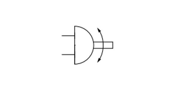
MSQX Series JIS symbol
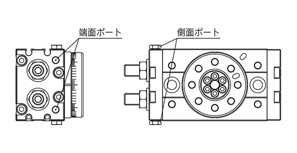
MSQX Series end port / side port diagrams
| Size | 10 | 20 | 30 | 50 | |
|---|---|---|---|---|---|
| Fluid | Air (non-lube) | ||||
| Max. operating pressure | 1 MPa | ||||
| Min. operating pressure | 0.1 MPa | ||||
| Ambient and fluid temperature | 0 to 60°C (no freezing) | ||||
| Cushion | None | ||||
| Angle adjustment range | 0 to 190 ° | ||||
| Maximum rotation angle | 190 ° | ||||
| Port size | End port | M5 × 0.8 | Rc1/8, G1/8, NPT1/8, NPTF1/8 | ||
| Side port | M5 × 0.8 | ||||
| Output (N·m)* | 0.89 | 1.8 | 2.7 | 4.6 | |
*Output under operating pressure of 0.5 MPa. See the manufacturer's catalog for details.
Allowable Kinetic Energy and Rotation Time Adjustment Range
Allowable kinetic energy
- Size 10: 0.007 J
- Size 20: 0.025 J
- Size 30: 0.048 J
- Size 50: 0.081 J
Stable operational rotation time adjustment range
- 1 to 5s/90 °
*If operated where the kinetic energy exceeds the allowable value, this may cause damage to the internal parts and result in product failure. Please pay special attention to the kinetic energy levels when designing, adjusting and during operation to avoid exceeding the allowable limit.
Weight
Basic type
- Size 10: 500 g
- Size 20: 940 g
- Size 30: 1,230 g
- Size 50: 1,990 g
*Values above do not include auto switch weight.
External dimensional drawing
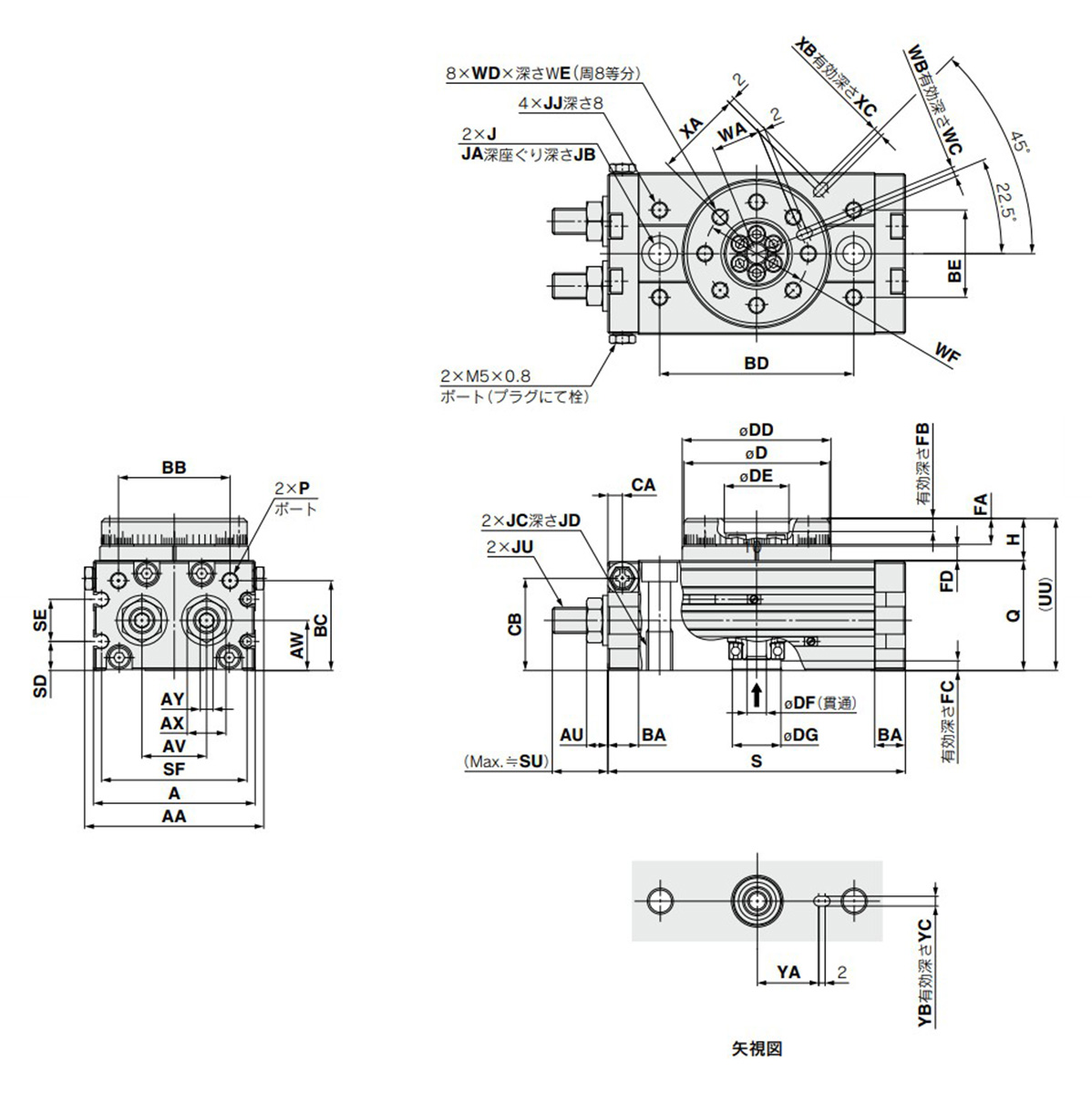
Basic / MSQXB□A dimensional drawing
(Unit: mm)
| Size | AA | A | AU | AV | AW | AX | AY | BA | BB | BC | BD | BE | CA | CB |
|---|---|---|---|---|---|---|---|---|---|---|---|---|---|---|
| 10 | 55.4 | 50 | 6.6 | 20 | 15.5 | 12 | 4 | 9.5 | 34.5 | 27.8 | 60 | 27 | 4.5 | 28.5 |
| 20 | 70.8 | 65 | 7.6 | 27.5 | 16 | 14 | 5 | 12 | 46 | 30 | 76 | 34 | 6 | 30.5 |
| 30 | 75.4 | 70 | 7.6 | 29 | 18.5 | 14 | 5 | 12 | 50 | 32 | 84 | 37 | 6.5 | 33.5 |
| 50 | 85.4 | 80 | 10 | 38 | 22 | 19 | 6 | 15.5 | 63 | 37.5 | 100 | 50 | 10 | 37.5 |
| Size | D | DD | DE | DF | DG | FA | FB | FC | FD | H | J | JA | JB |
|---|---|---|---|---|---|---|---|---|---|---|---|---|---|
| 10 | 45h9 | 46h9 | 20H9 | 6 | 15H9 | 8 | 4 | 3 | 4.5 | 13 | 6.8 | 11 | 6.5 |
| 20 | 60h9 | 61h9 | 28H9 | 9 | 17H9 | 10 | 6 | 2.5 | 6.5 | 17 | 8.6 | 14 | 8.5 |
| 30 | 65h9 | 67h9 | 32H9 | 12 | 22H9 | 10 | 4.5 | 3 | 6.5 | 17 | 8.6 | 14 | 8.5 |
| 50 | 75h9 | 77h9 | 35H9 | 13 | 26H9 | 12 | 5 | 3 | 7.5 | 20 | 10.5 | 18 | 10.5 |
(Unit: mm)
| Size | JC | JD | JJ | JU | P | Q | S | SD | SE | SF |
|---|---|---|---|---|---|---|---|---|---|---|
| 10 | M8 × 1.25 | 12 | M5 × 0.8 | M8 × 1 | M5 × 0.8 | 34 | 92 | 9 | 13 | 45 |
| 20 | M10 × 1.5 | 15 | M6 × 1 | M10 × 1 | M5 × 0.8 | 37 | 117 | 10 | 12 | 60 |
| 30 | M10 × 1.5 | 15 | M6 × 1 | M10 × 1 | Rc1/8** | 40 | 127 | 11.5 | 14 | 65 |
| 50 | M12 × 1.75 | 18 | M8 × 1.25 | M14 × 1.5 | Rc1/8** | 46 | 152 | 14.5 | 15 | 75 |
| Size | SU | UU | WA | WB | WC | WD | WE | WF | XA | XB | XC | YA | YB | YC |
|---|---|---|---|---|---|---|---|---|---|---|---|---|---|---|
| 10 | 17.7 | 47 | 15 | 3H9 | 3.5 | M5 × 0.8 | 8 | 32 | 27 | 3H9 | 3.5 | 19 | 3H9 | 3.5 |
| 20 | 25 | 54 | 20.5 | 4H9 | 4.5 | M6 × 1 | 10 | 43 | 36 | 4H9 | 4.5 | 24 | 4H9 | 4.5 |
| 30 | 25 | 57 | 23 | 4H9 | 4.5 | M6 × 1 | 10 | 48 | 39 | 4H9 | 4.5 | 28 | 4H9 | 4.5 |
| 50 | 31.4 | 66 | 26.5 | 5H9 | 5.5 | M8 × 1.25 | 12 | 55 | 45 | 5H9 | 5.5 | 33 | 5H9 | 5.5 |
**In addition to Rc1/8, G1/8, NPT1/8, NPTF1/8 are also available.
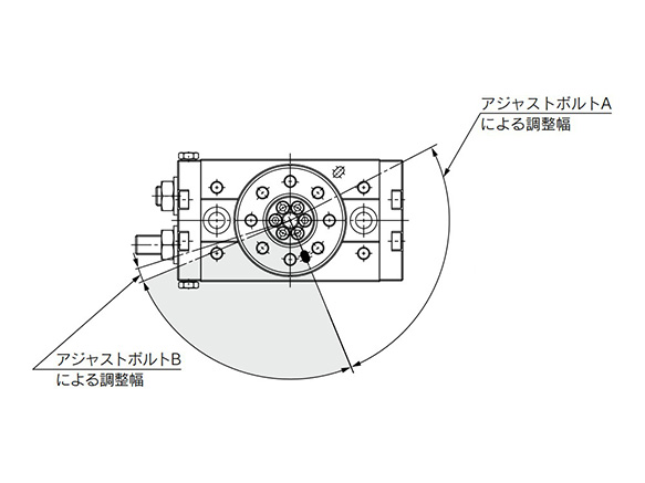
Rotation Direction and Rotation Angle
- The rotary table turns in the clockwise direction when the A port is pressurized, and in the counterclockwise direction when the B port is pressurized.
- By adjusting the adjustment bolt, the rotation end can be set within the range shown in the drawing for the desired rotation angle.
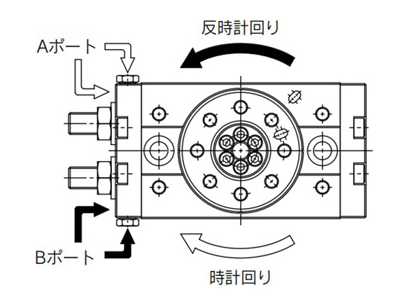
Diagram: rotation direction
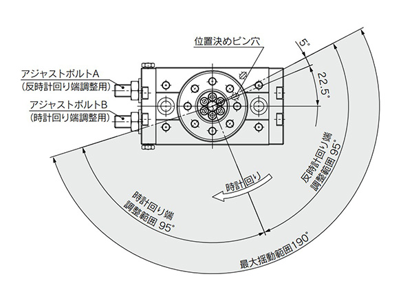
Diagram: rotation angle
- *The drawing shows the rotation range of the positioning pin hole.
- *The pin hole position in the drawing shows the counterclockwise rotation end when the adjustment bolts A and B are tightened equally and the rotation is adjusted 180°.
With external shock absorber / adjustment angle per rotation of angle adjusting screw
- Size 10: 10.2 °
- Size 20: 7.2 °
- Size 30: 6.5 °
- Size 50: 8.2 °
Rotation Angle Range Example
Various rotation ranges are possible as shown in the drawings below using adjustment bolts A and B.
(The drawings also show the rotation ranges of the positioning pin.)
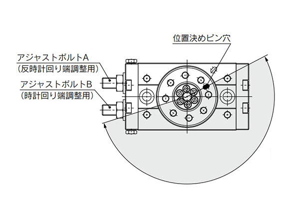
190° (maximum) rotation
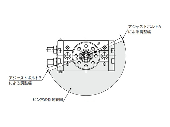
180° rotation
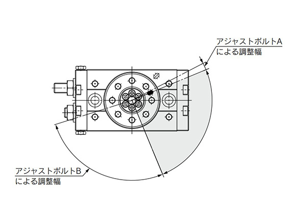
90° rotation
90° rotation
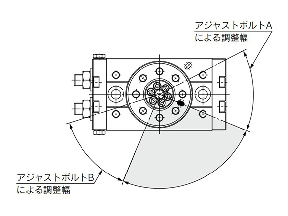
90° rotation
Precautions
Speed Adjustment
- *Changes in speed occur in applications in which there are changes to the load during operation, such as the load being lifted (lowered) against gravity.
- *The purpose of this product is stable rotation at low speed. It does not provide any function to cushion the impact at the operation start or end.
- *Speed may vary at the rotation end depending on operating conditions. (This can be avoided by setting the external stopper.)
*See the manufacturer's catalog for product information other than the above.