Basic Rotary Table, Vane Type, MSUB Series

Caution
- Refer to the catalog for details on product specifications.
- Product images may be representative. Refer to the manufacturer's catalog for details.
Product Description
A rotary actuator with a lightweight and compact table, suitable for robot hands.
[Features]
· Free mount type.
& nbspCan be mounted in 3 directions; axial, lateral, vertical.
· Single vane and double vane types now standard.
· The double vane type has the same dimensions as the single vane type.
Basic Rotary Table, Vane Type, MSUB Series Specifications

MSUB Series JIS symbol
| Model | MSUB1 | MSUB3 | |||||
|---|---|---|---|---|---|---|---|
| Vane type | Single vane | Double vane | Single vane | Double vane | |||
| Rotating angle*1 | 90° ±10 ° | 180° ±10 ° | 90° ±5 ° | 90° ±10 ° | 180° ±10 ° | 90° ±5 ° | |
| Fluid | Air (non-lube) | ||||||
| Proof pressure (MPa) | 1.05 | ||||||
| Ambient and fluid temperature | 5 to 60°C | ||||||
| Operating pressure range (MPa) | 0.2 to 0.7 | 0.15 to 0.7 | |||||
| Rotation time adjustment range (s/90) ° | 0.07 to 0.3 (0.5 MPa) | ||||||
| Shaft load | Allowable radial load | 20 N | 40 N | ||||
| Allowable thrust load*2 | 15 N | 30 N | |||||
| 10 N | 15 N | ||||||
| Allowable moment | 0.3 N·m | 0.7 N·m | |||||
| Shaft | Bearing | ||||||
| Port location | Side ported or axial ported | ||||||
| Port size | Side ported | M3 × 0.5 | M5 × 0.8 | ||||
| Axial ported | M3 × 0.5 | ||||||
| Model | MSUB7 | MSUB20 | |||||
|---|---|---|---|---|---|---|---|
| Vane type | Single vane | Double vane | Single vane | Double vane | |||
| Rotating angle*1 | 90° ±10 ° | 180° ±10 ° | 90° ±5 ° | 90° ±10 ° | 180° ±10 ° | 90° ±5 ° | |
| Fluid | Air (non-lube) | ||||||
| Proof pressure (MPa) | 1.05 | 1.5 | |||||
| Ambient and fluid temperature | 5 to 60°C | ||||||
| Operating pressure range (MPa) | 0.15 to 0.7 | 0.15 to 1.0 | |||||
| Rotation time adjustment range (s/90) ° | 0.07 to 0.3 (0.5 MPa) | ||||||
| Shaft load | Allowable radial load | 50 N | 60 N | ||||
| Allowable thrust load*2 | 60 N | 80 N | |||||
| 30 N | 40 N | ||||||
| Allowable moment | 0.9 N·m | 2.9 N·m | |||||
| Shaft | Bearing | ||||||
| Port location | Side ported or axial ported | ||||||
| Port size | Side ported | M5 × 0.8 | |||||
| Axial ported | M5 × 0.8 | ||||||
- *1 Single vane 90° can be adjusted to 90° ±10° (both ends of rotation ±5° each)
Single vane 180° can be adjusted to 180° ±10° (both ends of rotation ±5° each)
Double vane 90° can be adjusted to 90° ±5° (both ends of rotation ±2.5° each)
*Rotation angles other than 90° and 180° (single vane) are available by special order. - *2 The allowable thrust load is directional. Refer to the allowable load in the manufacturer's catalog for details.
Weight
(Unit: g)
| Size | Rotating angle | Basic weight | Auto switch unitNote ) | ||
|---|---|---|---|---|---|
| Single vane | Double vane | ||||
| 1 | 90 | 145 | 150 | 15 | |
| 180 | 140 | - | |||
| 3 | 90 | 230 | 240 | 20 | |
| 180 | 225 | - | |||
| 7 | 90 | 360 | 375 | 28 | |
| 180 | 355 | - | |||
| 20 | 90 | 510 | 580 | 38 | |
| 180 | 505 | - | |||
*Values above do not include auto switch weight.
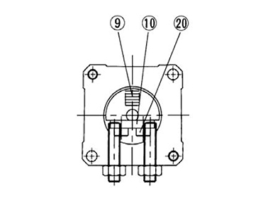
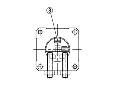
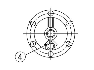
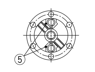
Structure drawing
Rotary Table Internal Structure Drawing
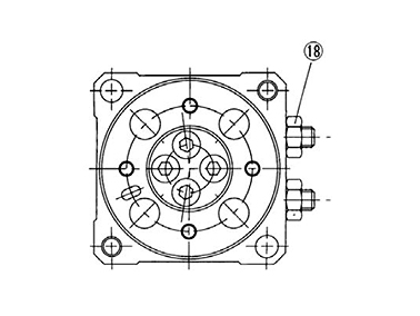
MSUB Series Rotary Table internal structure drawing 1
For 180° (figure in the middle position) structure drawing
For 90° (figure with pressure to A port) structure drawing
Single vane (for 180° figure in the middle position) structure drawing
Double vane (figure with pressure to A port) structure drawing
Single vane; size 1, 3, 7, 20 structure drawing
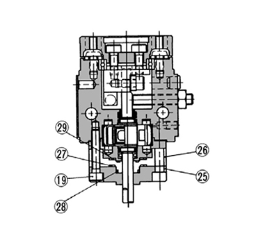
Double vane; size 1 structure drawing
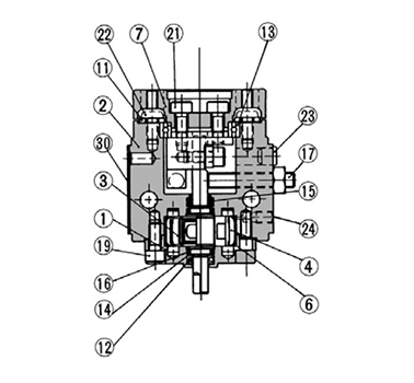
Double vane; size 3, 7, 20 structure drawing
| No. | Description | Material | Note |
|---|---|---|---|
| 1 | Body (A) | Aluminum alloy | Anodized |
| 2 | Body (B) | Aluminum alloy | Anodized |
| 3 | Vane shaft | Stainless steel (MSUB20 is carbon steel) | Single vane |
| Carbon steel | Double vane | ||
| 4 | Stopper | Resin | Single vane |
| 5 | Stopper | Stainless steel | Double vane |
| 6 | Stopper seal | NBR | - |
| 7 | Table | Aluminum alloy | Anodized, serigraph |
| 8 | Stopper lever (D) | Carbon steel | Heat treated, electroless nickel plated |
| 9 | Stopper lever (S) | Carbon steel | Heat treated, electroless nickel plated |
| 10 | Lever retainer | Carbon steel | Zinc chromated |
| 11 | Ring collar | Carbon steel | Zinc chromated |
| 12 | Bearing | High carbon chrome bearing steel | - |
| 13 | Bearing | High carbon chrome bearing steel | - |
| 14 | Back-up ring | Stainless steel | - |
| 15 | Scraper | NBR | - |
| 16 | O-ring | NBR | - |
| 17 | With adjustment bolt | Carbon steel | Heat treated |
| 18 | Hex nut | Carbon steel | - |
| 19 | Hex socket head cap screw | - | - |
| 20 | Hex socket head cap screw | - | - |
| 21 | Hex socket head cap screw | - | - |
| 22 | Button bolt | - | - |
| 23 | Rubber cap | NBR | - |
| 24 | Hex socket head set screw | - | SE type only |
| 25 | Cover | Aluminum alloy | - |
| 26 | Plate | Resin | - |
| 27 | Gasket | NBR | - |
| 28 | O-ring | NBR | - |
| 29 | O-ring | NBR | - |
| 30 | Label | - | - |
- *The plug (24) is used only when the connection port is type SE.
- *Individual part cannot be shipped.
External dimensional drawing
*These drawings indicate the state of the product when the B port is pressurized.
MSUB1 (single vane)
(Unit: mm)
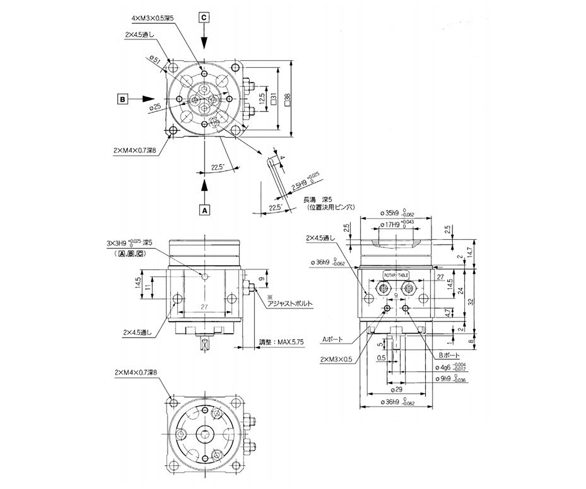
MSUB1-□S, SE dimensional drawing
(Unit: mm)

Axial ported / MSUB1-□SE dimensional drawing
*If the adjustment bolt is removed, rotation will be approximately 270° for the single vane type and 100° for the double vane type. Since this will make it impossible to satisfy the specifications, operate with adjustment within the range of maximum values.
Precautions
- *Be sure to read the precautions in the catalog before use.
- *See the manufacturer's catalog for information other than the above.