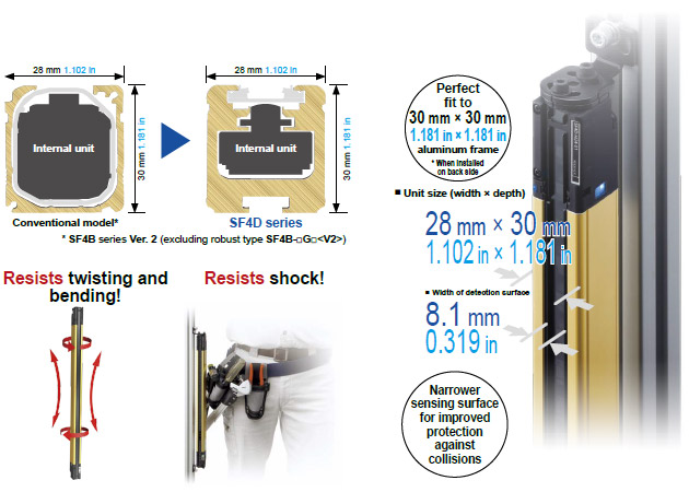
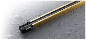
Slim and robust unit body resists twisting, warping and impact
Downsized internal unit, increased case thickness
The internal unit was redesigned and downsized extensively.
The internal unit was downsized to less than 40% (volume ratio) as compared to the conventional model while achieving higher performance.
The case structure was also optimized and offers high rigidity without any change in external dimensions.
The SF4D series provides high performance and high reliability while maintaining the installation and wiring compatibility with the previous models.
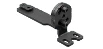
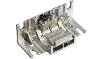
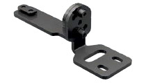
Mounting brackets feature both rigidity and ease of handling
Conventional model |
|---|
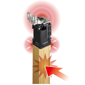 | Mounting brackets are attached to the top case and bottom case.
When the unit was subjected to intense shock, a large load was occasionally placed on the aluminum case joint. |
| SF4D series |
|---|
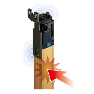 | The mounting brackets is attached to the back of the rigid aluminum case.
This reduces the load on the top case and bottom case, and helps prevent beam misalignment and failure due to shock. |
|
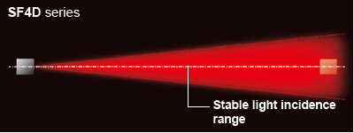
New high power optical system offering stable operation even for long distance setup
Increased power of emitter element
The power of the emitter has been increased significantly. The high resistance to dust and dirt contributes to the reduction of maintenance frequency.
| Minimization of deviations among elementsWe incorporated the element alignment technology that we cultivated for fiber sensors in the safety light curtain. This minimizes curves due to emitter and receiver mounting deviations and quality deviations due to differences in individual elements. Redesigned emitter element layout and structureThe scattering light energy from each emitter element is guided efficiently through the lens. The light energy of the emitter element is utilized fully, and the light distribution characteristics were optimized for the specific aperture angle.* |
* The aperture angle of a Type 4 safety light curtain is specified as a maximum of 2.5° each on the right and left at a detection distance of 3 m 9.843 ft or more. |
Shuts out liquids and dust IP67, IP65 (IEC) NEMA Type 13 (NEMA 250)
The SF4D series complies with IP67 and IP65 (IEC) as well as NEMA Type 13 (NEMA 250)*1.
The unit structure prevents the entry of not only water but also coolant and other liquids*2 to protect the internal unit.
| *1 | The SF4D series complies with the Type 13 requirements for non-explosion-proof enclosures specified in NEMA 250, "Enclosure for Electrical Equipment (1,000 V Maximum)," established by NEMA (National Electrical Manufacturers Association) in the United States.
Type 13: Enclosures for mainly indoor use which satisfy the following conditions:
・Prevention of incidental contact with the enclosed equipment
・Protection against falling dirt and protection against circulating airborne particles
・Protection against spraying, splashing and seepage of water and noncorrosive lubricants |
|---|
| *2 | If used in a place where cutting fluid can splash, additives in the fluid may cause degradation. Please check in advance whether the SF4D series is resistant to the specific cutting fluid used by your company. |
|---|
| |
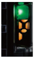
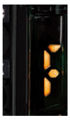
Digital indicator with a numeric display of light incidence margin facilitates beam axis adjustment and preventive maintenance.
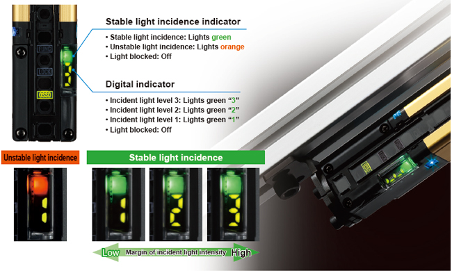
The light incidence margin is indicated by the “stable light incidence indicator” and “digital indicator”. This function enables appropriate beam adjustment and work quality control during installation of the device. The indicators also show whether there is dirt on the detection surface or beam misalignment due to play.
This enables the numeric display to be used for startup inspection and preventative maintenance.
* When optical synchronization is set, only the indicator on the receiver lights up.
Other features! Well-thought-out indicatorsThe indicators show stable light incidence status and notify various conditions. The OSSD indicator, interlock indicator and function setting indicator are arranged between the beam axes for easy visibility. | 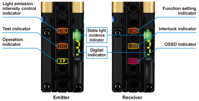 |
|
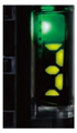
| Light incidence intensity indicationThe indicator shows the light incidence margin with a numeric display (1 to 3).
The displayed number decreases when there is dirt on the detection surface or beam axis misalignment occurs due to a loose mounting condition. This provides useful information during pre-operation inspection and preventive maintenance.
* Only the indicator on the receiver lights when optical synchronization is set. |
| Polarity indicationThe indicator shows the set polarity when power is turned on. This makes it easy to confirm proper operation after wiring. |
| Error indicationThe new series is also equipped with the error indication function, a well-received feature of our previous models. In an environment where a PC cannot be brought in or when a problem occurs at a remote location, the displayed error number lets you identify the cause of problem. This facilitates restoration work. |
Indicator for improved work efficiency
The application indicator improves work efficiency in a variety of ways by providing support to work activities ranging from daily equipment operation to installation and maintenance. The indicator function can be switched between two options.
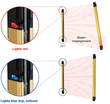
Beam axis adjustment modeThe color of the indicator notifies whether the beam axes of both top and bottom ends are aligned properly. The indicator is easy to see from any direction so mistakes can be prevented in a long-distance setup.
When beam axes of both top and bottom ends are aligned properly:
All application indicators light blue.
When beam axis of either of top end or bottom end is aligned:
All application indicators light blue.
When beam axis of either of top end or bottom end is aligned:
The indicators of only the aligned side light red.
When beam axes of both top and bottom ends are misaligned:
All application indicators are OFF. * When optical synchronization is set, only the indicator on the receiver lights up. |  |
|
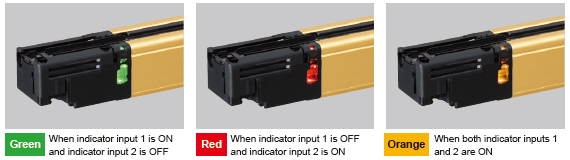
Application indicator mode
Can light and blink in three colors (green, red, and orange) according to an external input. The indicator can be used to indicate work instructions or equipment status.
| * | When optical synchronization is set, only the indicator on the receiver lights up. |
|---|
| * | The DIP switches in the unit must be set to use this function.
For details, see the manual. |
|---|
【COLUMN】
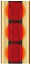
Stable light incidence indicator that even shows the amount of margin
The stable light incidence indicator is commonly used when installing a new safety light curtain to equipment or when checking if the existing safety light curtain is operating properly. Previously, however, even if the stable light incidence indicator was ON, there was no way of knowing whether there was an ample margin or the condition is close to unstable light incidence.
The SF4D series not only shows whether the light incidence is stable or unstable but also the amount of margin with a numeric display. Therefore, it is possible to numerically manage the stability margin of the safety light curtain. When the amount of received beam intensity decreases during equipment operation due to oil mist or other reasons, the digital display shows the stability margin of the safety light curtain. Thus, cleaning can be scheduled and conducted at the most suitable timing.
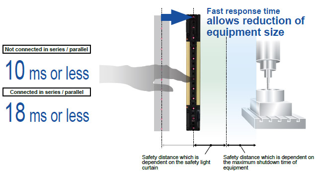
Response time is the fastest class in the industry*
The OFF response time of the control outputs (OSSD 1, OSSD 2) of the SF4D series is 10 ms or less, the fastest class* in the industry (when not connected in series or in parallel). [18 ms or less when connected in series or in parallel] The SF4D series contributes to the reduction of equipment size.
*As of September 2018, in-company survey
 | Regarding the response time by number of beams, see "Control output (OSSD 1, OSSD 2) OFF response times".
* As of September 2018, in-company survey |
|
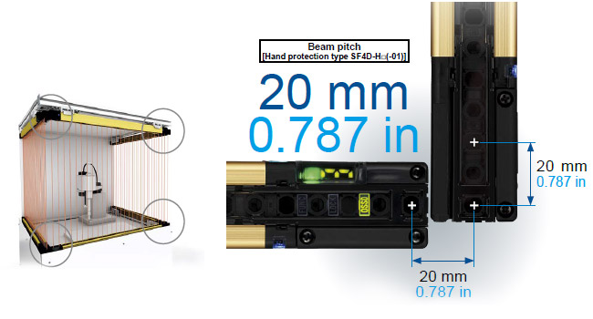
Dead zoneless design enables easy calculation of safe distance.
Inherits the dead zoneless design of the previous SF4B series. Even in an L-shaped layout or a U-shaped layout, the beam pitch does not cha
* Excluding the finger protection type SF4D-F□(-01).
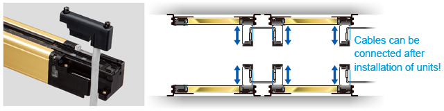
Easy to attach / detach front access cable
Uses the well-received front access cable of previous models. The cable can be attached and detached after the safety light curtain is installed on the equipment. This allows easy replacement in the event that the cable is damaged.
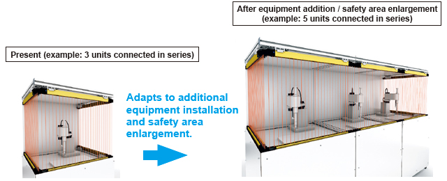
Series connection of up to 5 units
Up to five units (1 main sensor and 4 sub-sensors) can be connected in series, and the maximum number of beams has been increased to 256. This provides extra convenience when installing additional equipment, when increasing the detection width (protection height), and when using one system for protection of multiple locations.
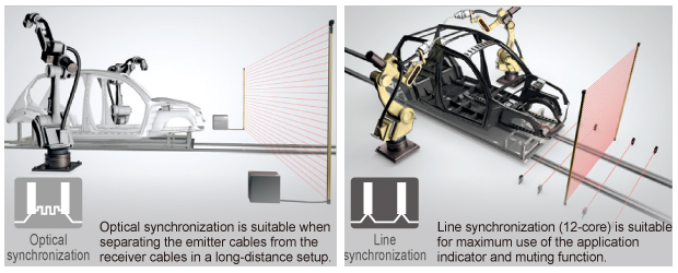
Selectable synchronization method and cable to suit various applications
When choosing and installing a safety light curtain, the synchronization method and cable can be selected flexibly according to the customer's specific application and needs, such as the basic configuration or safety-enhanced configuration with improved operability.
| Synchronization method | Optical
synchronization | Line
synchronization |
|---|
| Cable type | 5-core | 12-core | 8-core | 12-core |
|---|
| Function | Interlock function | | Software | ○(Software) | ○(Software) |
|---|
| Lockout release function | ○ | ○ | ○ | ○ |
|---|
| Test input function | ○ | ○ | ○ | ○ |
|---|
| Auxiliary output (non-safety output) function | | ○(Software) | ○(Software) | ○(Software) |
|---|
| External device monitor function | | ○(Software) | ○(Software) | ○(Software) |
|---|
| Muting / Override function | | Software | | ○(Software) |
|---|
| Application indicator function | Software | ○(Software) | Software | ○(Software) |
|---|
| Parallel interference prevention function | | | | Software |
|---|
| Fix blanking function | Software | Software | Software | Software |
|---|
| Floating blanking function | Software | Software | Software | Software |
|---|
| ○: | Functional by default |
|---|
| Software: | Functional when setting software is used |
|---|
| ○(Software): | Functional by default.
Function can be expanded when setting software is used |
|---|
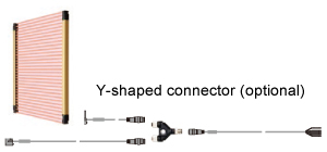
Y-shaped connector for further reduction of wiring
| When 8-core cables and line synchronization are used, connection of only five cables is required when the Y-shaped connector (optional) is used.
This allows easy connection to a safety PLC or other devices, and also helps eliminate wiring mistakes and reduce the man-hours required for wiring. |