Magnetically Coupled Rodless Cylinder, Slider Type: Slide Bearing, CY1S Series

Caution
- Refer to the catalog for product specifications.
- Product pictures are representations. CAD data is not supported by some of the model numbers.
Product Description
Air slide table made by SMC
[Features]
· Weight reduced by up to 15% (0.96 kg: conventionally 1.13 kg)
· Overall length reduced by up to 15 mm (240 mm: conventionally 255 mm)
· The inner and outer peripheral surfaces of the cylinder tube are equipped with Lub-retainers to improve lubricity retention.
· Stroke position reproducibility is improved with an adjusting bolt
Specifications of Magnet Type Rodless Cylinder, Slider Type / Slide Bearing CY1S Series
Model Number Notation

How to order: image
Applicable auto switches

Applicable auto switch part number identification, reference
- * 1The water resistant type auto switch can be mounted on the above models, but it does not guarantee the water-resistant performance of the product.
Check with the manufacturer regarding water-resistant types for the above model numbers. - * 2Lead wire length 1 m type is only compatible with D-A93.
- *Auto switches are shipped together (but not assembled).
Individual Made-to-Order Specifications

Reference for identifying the part number of individually made-to-order specifications
Made to Order Specifications

Reference for identifying the part number for made-to-order specifications
Specifications Table
| Tube Internal Diameter (mm) | 6 | 10 | 15 | 20 | 25 | 32 | 40 |
|---|---|---|---|---|---|---|---|
| Fluid | Air | ||||||
| Proof Pressure | 1.05 MPa | ||||||
| Maximum operating pressure | 0.7 MPa | ||||||
| Minimum operating pressure | 0.18 MPa | ||||||
| Ambient and fluid temperature | -10°C to +60°C (no freezing) | ||||||
| * Piston Speed | 50 to 400 mm/s | ||||||
| Cushioning | Rubber cushion / shock absorber | ||||||
| Lubrication | Not required | ||||||
| Stroke Length Tolerance (mm) | 0-250st: 0 to +1.0, 251 to 1,000st: 0 to +1.4, 1,001st to: 0~+1.8 | ||||||
| Magnetic retention force (N) | 19.6 | 53.9 | 137 | 231 | 363 | 588 | 922 |
- * When setting the auto switch to the intermediate position, the maximum piston speed that can be detected is restricted by the response time of the load (relay, sequence controller, etc.).
Standard Stroke Table
| Tube Internal Diameter (mm) | Standard Stroke (mm) | Manufacturable Maximum stroke (mm) |
|---|---|---|
| 6 | 50, 100, 150, 200 | 300 |
| 10 | 50, 100, 150, 200, 250, 300 | 500 |
| 15 | 50, 100, 150, 200, 250, 300, 350, 400, 450, 500 | 750 |
| 20 | 100, 150, 200, 250, 300, 350, 400, 450, 500, 600, 700, 800 | 1,000 |
| 25 | 1,500 | |
| 32 | ||
| 40 | 100, 150, 200, 250, 300, 350, 400, 450, 500, 600, 700, 800, 900, 1,000 | 1,500 |
- * *1) The minimum manufacturable stroke is up to 15st without a switch or with 1 switch, and up to 25st with 2 switches.
- * *2) If there are multiple switches and the stroke is shorter than 25st (up to 15st), consider X431 (2 switch rail types).
Weight Table
(Unit: kg)
| Tube Internal Diameter (mm) | 6 | 10 | 15 | 20 | 25 | 32 | 40 | |
|---|---|---|---|---|---|---|---|---|
| CY1S□ | Basic weight | 0.231 | 0.428 | 0.743 | 1.317 | 1.641 | 2.870 | 4.508 |
| Additional weight per 50 strokes | 0.053 | 0.082 | 0.111 | 0.184 | 0.186 | 0.284 | 0.430 | |
| CY1SG□ | Basic weight | 0.236 | 0.435 | 0.743 | 1.331 | 1.662 | 2.903 | 4.534 |
| Additional weight per 50 strokes | 0.050 | 0.079 | 0.108 | 0.176 | 0.178 | 0.273 | 0.411 | |
Calculation method/example: CY1SG25-500
Basic weight (At 0 stroke): 1.662 kg / additional weight per 50 strokes: 0.178 kg
Cylinder Stroke: 500st
1.662 + 0.178×500 ÷ 50 = 3.442 kg
Shock Absorber Specifications
| Compatible cylinder | CY1S□6 | CY1S□10 | CY1S□15 | CY1S□20 | CY1S□25 | CY1S□32 | CY1S□40 |
|---|---|---|---|---|---|---|---|
| Shock absorber model | RJ0604 | RJ0806H | RJ0806L | RJ1007L | RJ1412L | RJ2015H | RJ2015L |
| Maximum energy absorption (J) | 0.5 | 1 | 3 | 10 | 30 | ||
| Stroke absorption (mm) | 4 | 6 | 7 | 12 | 15 | ||
| Collision speed (m/s) | 0.05 to 1 | 0.05 to 2 | 0.05 to 1 | 0.05 to 1 | 0.05 to 1 | 0.05 to 2 | 0.05 to 1 |
| Maximum frequency of use (cycle/min) | 80 | 80 | 70 | 45 | 25 | ||
| Max. allowable thrust (N) | 150 | 245 | 422 | 814 | 1961 | ||
| Ambient Temperature (°C) | -10°C to +60°C (no freezing) | ||||||
* *) The maximum absorbed energy and maximum frequency of use are the values at room temperature (approximately 20 to 25°C).
Diagram

CY1S / both sides piping type configuration diagram

Structural drawing of CY1SG / Centralized piping type
Components
| Number | Name | Material | Note |
|---|---|---|---|
| 1 | Magnet A | - | - |
| 2 | Piston-Side Yoke | Rolled steel | - |
| 3 | Piston | Aluminum alloy | - |
| *4 | Piston packing | NBR | - |
| *5 | Wear Ring A | Special resin | - |
| *6 | Lube-retainer A | Special resin | Excluding ø6 (diameter 6 mm) and ø10 (diameter: 10 mm) |
| 7 | Shaft | Stainless steel | - |
| 8 | Piston Nut | Carbon steel | Except ø6 (diameter: 6 mm) to ø15 (diameter: 15 mm) |
| 9 | Slide block | Aluminum alloy | - |
| 10 | Bushing | Resin/Copper alloy (Multiple layers) | - |
| 11 | Parallel pin | Carbon steel | - |
| 12 | Moving element spacer | Rolled steel | - |
| *13 | Mover gasket | NBR | - |
| 14 | Retaining Ring | Carbon tool steel | - |
| 15 | Magnet for switches | - | - |
| 16 | External Slider Tube | Aluminum alloy | - |
| 17 | Magnet B | - | - |
| 18 | External Slider Side Yoke | Rolled steel | - |
| *19 | Wear Ring B | Special resin | - |
| *20 | Lube-retainer B | Special resin | Except ø6 (diameter: 6 mm) |
| 21 | Spacer | Rolled steel | Except ø6 (diameter: 6 mm) |
| 22 | Plate A | Aluminum alloy | - |
| 23a | Plate C | Aluminum alloy | For piping on both sides |
| 23b | Plate B | Aluminum alloy | For centralized piping |
| *24 | Cylinder Tube Gasket | NBR | - |
| 25 | Bumper bolt | Chrome molybdenum steel | - |
| 26 | Damper | Urethane rubber | - |
| 27 | Cylinder Tube | Stainless steel | - |
| 28 | Guide shaft B | Carbon steel | Hard chrome plating |
| 29a | Guide shaft C | Carbon steel | Hard chrome plating |
| 29b | Guide shaft A | Carbon steel | Hard chrome plating |
| 30 | Switch rail | Aluminum alloy | - |
| 31 | Hex Socket Head Set Screw | Chrome molybdenum steel | - |
| 32 | Hex Socket Head Cap Screw | Chrome molybdenum steel | - |
| 33 | Hex Nut | Chrome molybdenum steel | - |
| 34 | Hex Nut | Chrome molybdenum steel | - |
| 35 | Square Nut | Chrome molybdenum steel | - |
| 36 | Cross-head machine screw with SW | Chrome molybdenum steel | - |
| 37 | Switch spacer | Special resin | - |
| 38 | Port plug | Chrome molybdenum steel | ø6 (diameter: 6 mm), piping on both sides only |
| *39 | Guide shaft gasket | NBR | For centralized piping |
| 40 | Steel ball | Bearing steel | For centralized piping |
| 41 | Adjusting bolt | Chrome molybdenum steel | - |
| 42 | Auto switch | - | - |
| 43 | Shock absorber | - | - |
| 44 | Liner | Aluminum alloy | - |
- * *1) The contents of the parts of the seal set are * -marked.
- * *2) Auto switch and switch spacer are shipped together.
Packing set
| Tube inner diameter (mm) | Packing set | |
|---|---|---|
| Part No. | Details | |
| 6 | CY1S6-Z-PS | Above number 4, 5, 13, 19, 24, 39 |
| 10 | CY1S10-Z-PS | Above number 4, 13, 19, 20, 24, 39 |
| 15 | CY1S15-Z-PS | Above number 4, 5, 6, 13, 19, 20, 24, 39 |
| 20 | CY1S20-Z-PS | |
| 25 | CY1S25-Z-PS | |
| 32 | CY1S32-Z-PS | |
| 40 | CY1S40-Z-PS | |
- * *1) For the seal kit, the ø6 kit (inner diameter: 6 mm) includes 4, 5, 13, 19, 24, 39, and the ø10 kit (inner diameter: 10 mm) includes 4, 13, 19, 20, 24, 39, the kits for ø15 (inner diameter: 15 mm) to ø40 (inner diameter: 40 mm) include 4, 5, 6, 13, 19, 20, 24, 39 in 1 set, so please order using the order number for each tube inner diameter.
- * *2) A grease pack (10 g) is attached to the seal kit.
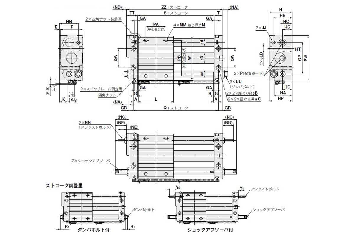
Dimensions of Magnet Type Rodless Cylinder, Slider Type / Slide Bearing CY1S Series
CY1S / both sides piping type
(Units: mm)

Dimensional drawing of CY1S / both sides piping type
(Units: mm)

Image of dimensions table for CY1S / both sides piping type
- * *) The above figure shows the case where the auto switch is installed. The auto switch and switch spacer are shipped together.
CY1SG / Centralized piping type
(Units: mm)
Dimensional drawing of CY1SG / Centralized piping type
(Units: mm)

Image of dimensions table for CY1SG / centralized piping type
- * *) The above figure shows the case where the auto switch is installed. The auto switch and switch spacer are shipped together.
Please refer to the table below for details about lead wire / connector specifications.
