Magnetically Coupled Rodless Cylinder, Direct Mount Type, CY3R Series

Caution
- Refer to the catalog for product specifications.
- Product pictures are representations. CAD data is not supported by some of the model numbers.
Product Description
An air slide table made by SMC
[Features]
· A further upgrade from the CY1 series
· The installation dimensions are the same as the CY1 series, yet it features improved bearing performance and reduced sliding resistance.
· NPT screws and G screws are standardized
Details of Magnet Type Rodless Cylinder, Direct Mount Type CY3R Series

Magnet Type Rodless Cylinder, Direct Mount Type CY3R Series product image
Specifications of Magnet Type Rodless Cylinder, Direct Mount Type CY3R Series
| Tube Internal Diameter (mm) | 6 | 10 | 15 | 20 | 25 | 32 | 40 | 50 | 63 |
|---|---|---|---|---|---|---|---|---|---|
| Fluid | Air | ||||||||
| Proof Pressure | 1.05 MPa | ||||||||
| Maximum operating pressure | 0.7 MPa | ||||||||
| Minimum operating pressure | 0.16 | 0.16 | 0.16 | 0.16 | 0.15 | 0.14 | 0.12 | 0.12 | 0.12 |
| Ambient and fluid temperature | -10°C to 60°C (no freezing) | ||||||||
| *) Piston speed used | 50 to 500 mm/s | ||||||||
| Cushioning | Rubber cushion | ||||||||
| Lubrication | Not required (non-lubricated) | ||||||||
| Stroke Length Tolerance (mm) | 0 to 250 st: (0 to +1.0), 251 to 1,000 st: (0 to +1.4), 1,001 st and above: (0 to +1.8) | ||||||||
| Mounting Methods | Direct mount type | ||||||||
| Mounting orientation | Horizontal, inclined, vertical *2) | ||||||||
| Magnetic retention force (N) | 19.6 | 53.9 | 137 | 231 | 363 | 588 | 922 | 1,471 | 2,256 |
*1) For models with an auto switch, when setting the auto switch in the intermediate position, set the maximum piston speed to 300 mm/s or less in consideration of the relay, etc.
*2) In the case of vertical mounting, an intermediate stop by the pneumatic circuit is not possible.
Model Number Notation
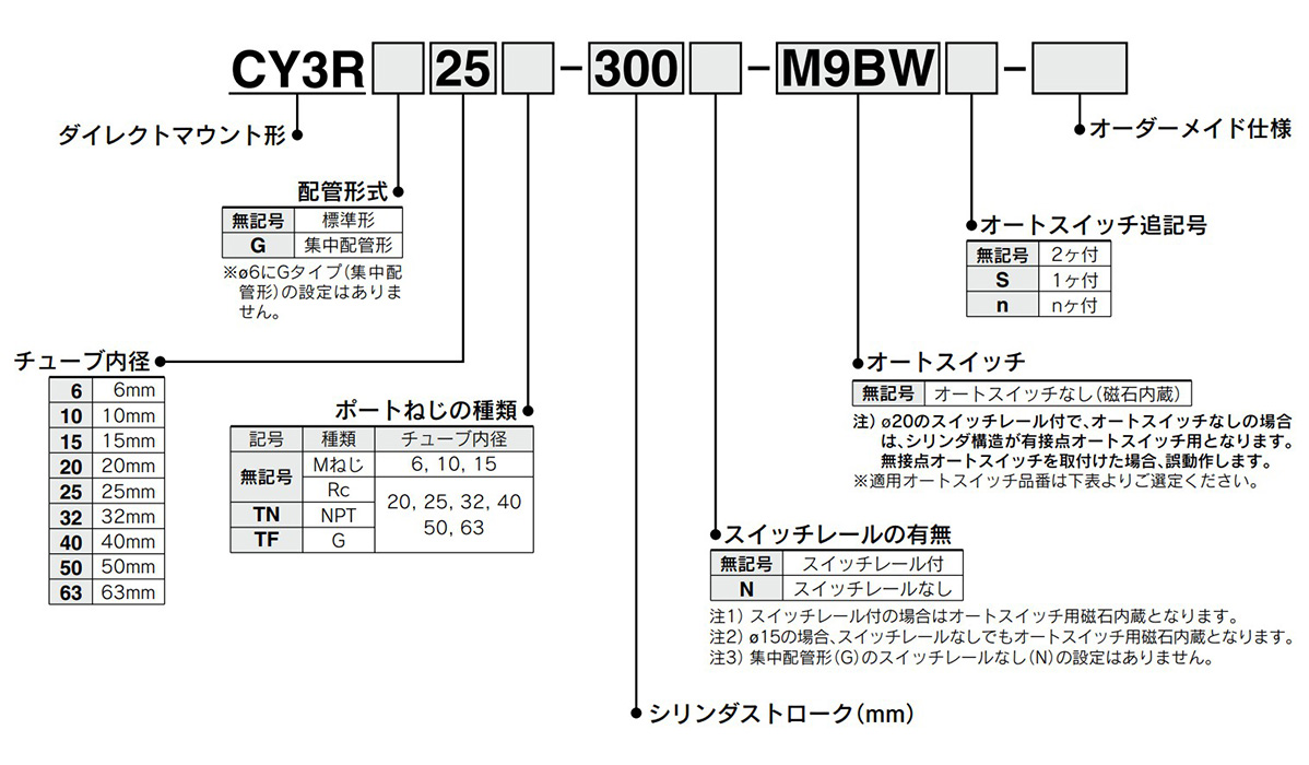
Model number examples
Applicable auto switches
| Auto Switch Unit Part Number | Type | Special Functions | Electrical Entry | Indicator light | Wiring (Output) | Load voltage | ||
|---|---|---|---|---|---|---|---|---|
| DC | AC | |||||||
| M9N | Solid State Auto Switch | - | Grommet | Yes | 3-wire (NPN) | 24 V | 5 V, 12 V | - |
| M9P | 3-wire (PNP) | |||||||
| M9B | 2-wire | 12 V | ||||||
| M9NW | Diagnostic indication (2-color indicator) | 3-wire (NPN) | 5V, 12V | |||||
| M9PW | 3-wire (PNP) | |||||||
| M9BW | 2-wire | 12V | ||||||
| * 1M9NA | Water-resistant (2-color indicator) | 3-wire (NPN) | 5V, 12V | |||||
| * 1M9PA | 3-wire (PNP) | |||||||
| * 1M9BA | 2-wire | 12V | ||||||
| A96 | Reed type auto switch | - | Grommet | Yes | 3-wire (NPN equivalent) | - | 5 V | - |
| A93 | 2-wire | 24V | 5V, 12V | 100 V | ||||
| A90 | No | 100 V or less | ||||||
| Auto Switch Unit Part Number | Lead Wire Length (m) | Pre-Wired Connector | Applicable load | ||||
|---|---|---|---|---|---|---|---|
| 0.5 (Nil) | 1 (M) | 3 (L) | 5 (Z) | ||||
| M9N | ● | ● | ● | ○ | ○ | IC circuit | Relay, PLC |
| M9P | ● | ● | ● | ○ | ○ | ||
| M9B | ● | ● | ● | ○ | ○ | - | |
| M9NW | ● | ● | ● | ○ | ○ | IC circuit | |
| M9PW | ● | ● | ● | ○ | ○ | ||
| M9BW | ● | ● | ● | ○ | ○ | - | |
| * 1M9NA | ○ | ○ | ● | ○ | ○ | IC circuit | |
| * 1M9PA | ○ | ○ | ● | ○ | ○ | ||
| * 1M9BA | ○ | ○ | ● | ○ | ○ | - | |
| A96 | ● | - | ● | - | - | IC circuit | - |
| A93 | ● | ● | ● | ● | - | Relay, PLC | |
| A90 | ● | - | ● | - | - | - | |
- * 1The water resistant type auto switch can be mounted on the above models, but it does not guarantee the water-resistant performance of the product. Check with the manufacturer regarding water-resistant types for the above model numbers.
- * Lead wire length symbol 0.5 m, No symbol (Example) M9NW; 1 m, M (Example) M9NWM; 3 m, L (Example) M9NWL; 5 m, Z (Example) M9NWZ
- *Solid state auto switches marked with ○ are produced to order.
- *Auto switches are shipped together (but not assembled).
Diagram Examples
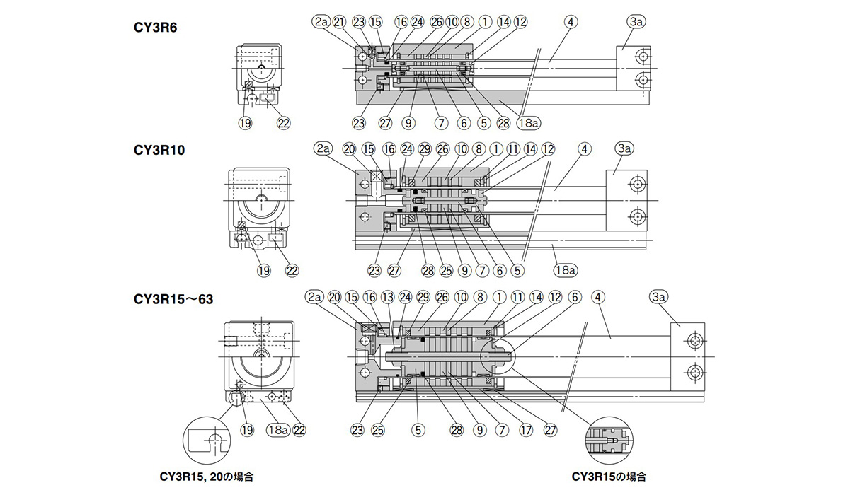
Structural drawing of double-sided piping
Components
| Number | Part Name | Material | Note | ||
|---|---|---|---|---|---|
| 1 | Body | Aluminum alloy | Hard anodized aluminum | ||
| 2a | End cover A | Aluminum alloy | - | ||
| 2b | End cover C | Aluminum alloy | - | ||
| 3a | End cover B | Aluminum alloy | - | ||
| 3b | End cover D | Aluminum alloy | - | ||
| 4 | Cylinder Tube | Stainless steel | - | ||
| 5 | Piston | ø6 (diameter 6 mm) | Brass | ø6 (diameter 6 mm) | Electroless nickel plating |
| ø10 to 63 (Diameter: 10 to 63 mm) | Aluminum alloy | ø10 to 63 (Diameter: 10 to 63 mm) | Chromate | ||
| 6 | Shaft | Stainless steel | - | ||
| 7 | Piston-Side Yoke | Rolled steel plate | Zinc chromate | ||
| 8 | External Slider Side Yoke | Rolled steel plate | Zinc chromate | ||
| 9 | Magnet A | - | - | ||
| 10 | Magnet B | - | - | ||
| 11 | Spacer | Aluminum alloy | No ø6 (diameter: 6 mm) | ||
| 12 | Damper | Urethane rubber | - | ||
| 13 | Piston Nut | Carbon steel | Zinc chromate (without ø6 to 15 (diameter: 6 to 15 mm)) | ||
| 14 | Type C Retaining Ring for Hole | Carbon tool steel | Phosphate Coated | ||
| 15 | Attachment Ring | Aluminum alloy | Chromate | ||
| 16 | Type C Retaining Ring for Shaft | High carbon steel wire material | - | ||
| 17 | Magnetic Shielding Plate | Rolled steel plate | Bright chromate (without ø6 (diameter: 6 mm), ø10 (diameter: 10 mm)) | ||
| 18a | Switch rail (Dual-side piping) | Aluminum alloy | Clear anodizing | ||
| 18b | Switch rail (Centralized piping) | Aluminum alloy | Clear anodizing | ||
| 19 | Magnet | - | - | ||
| 20 | Hexagon socket head plug | Chromium steel | Nickel plated | ||
| 21 | Steel ball | Chromium steel | ø40 (Diameter: 40 mm) | Hexagon socket head plug | |
| ø20 (diameter: 20 mm), ø50 (diameter: 50 mm), ø63 (Diameter: 63 mm) | None | ||||
| 22 | Hex Socket Head Cap Screw | Chromium steel | Nickel plated | ||
| 23 | Hex Socket Set Screw | Chromium steel | Nickel plated | ||
| 24 | Cylinder tube gasket | NBR | - | ||
| 25 | Wear Ring A | Special resin | ø6 (diameter: 6 mm) None | ||
| 26 | Wear Ring B | Special resin | - | ||
| 27 | Wear Ring C | Special resin | - | ||
| 28 | Piston packing | NBR | - | ||
| 29 | Lub-retainer | Special resin | ø6 (diameter: 6 mm) None | ||
| 30 | Switch rail gasket | NBR | Not available for piping on both sides | ||
Dimensions example of Magnet Type Rodless Cylinder, Direct Mount Type CY3R Series
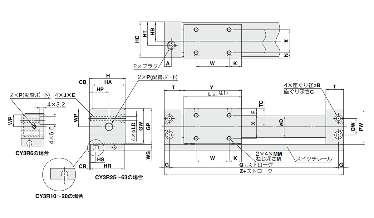
Both sides piping type: Dimensional drawing of ø6 (diameter 6 mm) to ø63 (diameter: 63 mm)
*1) ø50 (diameter: 50 mm) and ø63 (diameter: 63 mm) are L (-0.2 to 0).
(Units: mm)
| Model | A | B | C | CB | CR | D | F | G | GP | GW | H | HA | HB | HC | HP | HR | HS | HT | J × E | K |
|---|---|---|---|---|---|---|---|---|---|---|---|---|---|---|---|---|---|---|---|---|
| CY3R6 | 7 * | - * | - * | 2 | 0.5 | 7.6 | 5.5 | 3 * | 20 | 18.5 | 19 | 17 | 10.5 | 18 | 10.5 * | 17 | 6 | 10.5 * | M4 × 0.7 × 6 | 7 |
| CY3R10 | 9 | 6.5 | 3.2 | 2 | 0.5 | 12 | 6.5 | 4 | 27 | 25.5 | 26 | 24 | 14 | 25 | 14 | 24 | 5 | 14 | M4 × 0.7 × 6 | 9 |
| CY3R15 | 10.5 | 8 | 4.2 | 2 | 0.5 | 16.6 * | 8 | 5 | 33 | 31.5 | 32 | 30 | 17 | 31 | 17 | 30 | 8.5 | 17 | M5 × 0.8 × 7 | 14 |
| CY3R20 | 9 | 9.5 | 5.2 | 3 | 1 | 21.6 * | 9 | 6 | 39 | 37.5 | 39 | 36 | 21 | 38 | 24 | 36 | 7.5 | 24 | M6 × 1 × 8 | 11 |
| CY3R25 | 8.5 | 9.5 | 5.2 | 3 | 1 | 26.4 * | 8.5 | 6 | 44 | 42.5 | 44 | 41 | 23.5 | 43 | 23.5 | 41 | 6.5 | 23.5 | M6 × 1 × 8 | 15 |
| CY3R32 | 10.5 | 11 | 6.5 | 3 | 1.5 | 33.6 * | 10.5 | 7 | 55 | 53.5 | 55 | 52 | 29 | 54 | 29 | 51 | 7 | 29 | M8 × 1.25 × 10 | 13 |
| CY3R40 | 10 | 11 | 6.5 | 5 | 2 | 41.6 * | 13 | 7 | 65 | 63.5 | 67 | 62 | 36 | 66 | 36 | 62 | 8 | 36 | M8 × 1.25 × 10 | 15 |
| CY3R50 | 14 | 14 | 8.2 | 5 | 2 | 52.4 * | 17 | 8.5 | 83 | 81.5 | 85 | 80 | 45 | 84 | 45 | 80 | 9 | 45 | M10 × 1.5 × 15 | 25 |
| CY3R63 | 15 | 14 | 8.2 | 5 | 3 | 65.4 * | 18 | 8.5 | 95 | 93.5 | 97 | 92 | 51 | 96 | 51 | 90 | 9.5 | 51 | M10 × 1.5 × 15 | 24 |
(Units: mm)
| Model | L | LD | M | MM | N | PW | Q | QW | T | TC | W | WP | WS | X | Y | Z |
|---|---|---|---|---|---|---|---|---|---|---|---|---|---|---|---|---|
| CY3R6 | 34 | 3.5 | 3.5 | M3 × 0.5 | 3.5 | 19 | 60 * | 10 | 14.5 * | 10.5 | 20 | 9.5 | 6 | 10 | 35.5 | 66 * |
| CY3R10 | 38 | 3.5 | 4 | M3 × 0.5 | 4.5 | 26 | 68 | 14 | 17.5 | 14 | 20 | 13 | 8 | 15 | 39.5 | 76 |
| CY3R15 | 53 | 4.3 | 5 | M4 × 0.7 | 6 | 32 | 84 | 18 | 19 | 17 | 25 | 16 | 7 | 18 | 54.5 | 94 |
| CY3R20 | 62 | 5.4 | 5 | M4 × 0.7 | 7 | 38 | 95 | 17 | 20.5 | 20 | 40 | 19 | 7 | 22 | 64 | 107 |
| CY3R25 | 70 | 5.4 | 6 | M5 × 0.8 | 6.5 | 43 | 105 | 20 | 21.5 | 22.5 | 40 | 21.5 | 7 | 28 | 72 | 117 |
| CY3R32 | 76 | 7 | 7 | M6 × 1 | 8.5 | 54 | 116 | 26 | 24 | 28 | 50 | 27 | 7 | 35 | 79 | 130 |
| CY3R40 | 90 | 7 | 8 | M6 × 1 | 11 | 64 | 134 | 34 | 26 | 33 | 60 | 32 | 7 | 40 | 93 | 148 |
| CY3R50 | 110 | 8.6 | 10 | M8 × 1.25 | 15 | 82 | 159 | 48 | 30 | 42 | 60 | 41 | 10 | 50 | 113 | 176 |
| CY3R63 | 118 | 8.6 | 10 | M8 × 1.25 | 16 | 94 | 171 | 60 | 32 | 48 | 70 | 47 | 10 | 60 | 121 | 188 |
(Units: mm)
| Model | P (piping port) | ||
|---|---|---|---|
| Blank | TN * | TF * | |
| CY3R6 | M3 × 0.5 * | - | - |
| CY3R10 | M5 × 0.8 | - | - |
| CY3R15 | M5 × 0.8 | - | - |
| CY3R20 | Rc 1/8 | NPT1/8 | G1/8 |
| CY3R25 | Rc 1/8 | NPT1/8 | G1/8 |
| CY3R32 | Rc 1/8 | NPT1/8 | G1/8 |
| CY3R40 | Rc 1/4 | NPT1/4 | G1/4 |
| CY3R50 | Rc 1/4 | NPT1/4 | G1/4 |
| CY3R63 | Rc 1/4 | NPT1/4 | G1/4 |
*2) The asterisk (*) indicates dimensions different from the CY1R series.
Please refer to the table below for details about lead wire / connector specifications.
