2-Color Display High-Precision Digital Pressure Switch ZSE40A(F)/ISE40A Series

Caution
- See catalog for specification details.
- Product pictures are representations. CAD data is not supported for some model numbers.
Product Description
A pressure switch made by SMC.
[Features]
· Applicable fluids: Air, non-corrosive gas, non-flammable gas
· Can copy up to 10 switches simultaneously
· Easy handling.
Raised rubber switch buttons for easy and comfortable operation
· 3-step setting
· 2-color display
Specifications of 2-Color Display, High-Precision Digital Pressure Switch ZSE40A (F) / ISE40A Series
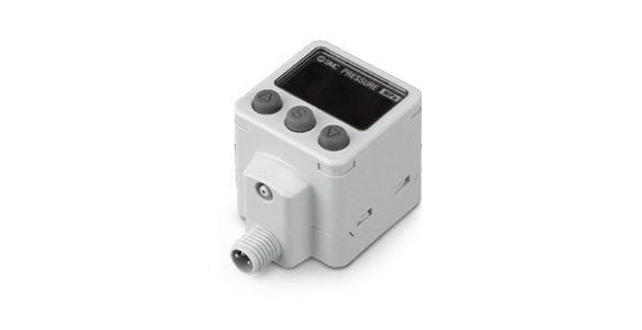
External appearance of M8 (3 pin) connector
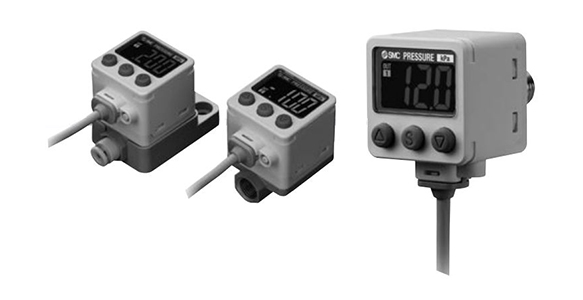
External appearance of ZSE40A (F) / ISE40A Series
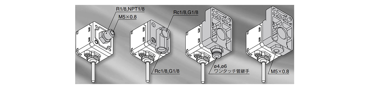
Piping variation
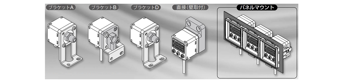
Mounting variation
* It is compatible with the ZSE40/ISE40 Series.
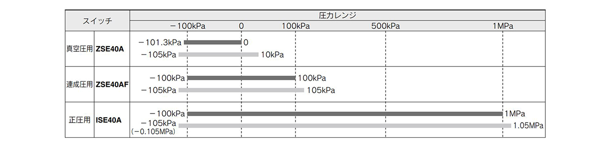
Specifications
| Model | ZSE40A (Vacuum Pressure) | ZSE40AF (Compound pressure) | ISE40A (Positive pressure) | ||
|---|---|---|---|---|---|
| Rated pressure range | 0.0 to -101.3 kPa | -100.0 to +100.0 kPa | -0.100 to +1.000 MPa | ||
| Display / Set pressure range | +10.0 to -105.0 kPa | -105.0 to +105.0 kPa | -0.105 to +1.050 MPa | ||
| Withstand pressure | 500 kPa | 500 kPa | 1.5 MPa | ||
| Display / Minimum set unit | 0.1 kPa | 0.1 kPa | 0.001 MPa | ||
| Fluid | Air, non-corrosive gases, nonflammable gas | ||||
| Power supply voltage | 12 to 24 V DC ±10% ripple (p-p) 10% or less (With reverse connection protection) | ||||
| Current Consumption | 45 mA or less | ||||
| Switch output | NPN or PNP open collector 1 output or 2 outputs | ||||
| - | Maximum load current | 80 mA | |||
| Maximum applied voltage | 28 V (with NPN output) | ||||
| Residual voltage | 1 V or less | ||||
| Response Time | 2.5 ms (Anti-chattering function 20, 100, 500, 1,000, 2,000 ms selectable) | ||||
| Short-circuit protection | Yes | ||||
| Repeatability | ±0.2% F.S. ±1 digit | ||||
| Hysteresis | Hysteresis mode | Variable from 0 *1) | |||
| Window Comparator Mode | |||||
| Analog output | Voltage output *2) | Output Voltage (Rated Pressure Range) | 1 to 5 V ±2.5% F.S. | 0.6 to 5 V±2.5%F.S. | |
| Linearity | ±1% F.S. | ||||
| Output Impedance | Approx. 1 kΩ | ||||
| Current output *3) | Output current (rated pressure range) | 4 to 20 mA ±2.5% F.S. | 2.4 to 20 mA ±2.5% F.S. | ||
| Linearity | ±1% F.S. | ||||
| Load impedance | Maximum load impedance Power supply voltage 12 V: 300 Ω Maximum load impedance Power supply voltage 24 V: 600 Ω Minimum load impedance 50 Ω | ||||
| Auto-shift input | Dry input (reed or non-contact), Low level 0.4 V or less, input time 5 ms or more | ||||
| Display | 3 1/2-digit 7-segment LCD 2-color display (Red/green) | ||||
| Display accuracy | ±2% F.S. ±1 digit (with ambient temperature of 25°C ±3°C) | ||||
| Indicator light | Lights up when switch output is turned ON, OUT1, OUT2: Orange | ||||
| Environment | Protective Enclosure | IP65 | |||
| Operating temperature range *4) | During operation: -5 to +50°C, during storage: -10~+60℃ (No condensation or freezing) | ||||
| Operating Humidity Range | Operating/stored: 35 to 85% RH (no condensation) | ||||
| Withstand Voltage | 1,000 V AC for 1 min. between terminals and housing | ||||
| Insulation Resistance | 50 MΩ or more (500 V DC measured via insulation resistance tester) between terminals and housing | ||||
| Temperature characteristics | ±2% F.S. (based on 25°C) | ||||
| Lead | Oil resistant vinyl flexible cable 5 cores | ||||
| ø3.5 (diameter: 3.5 mm) 2 m Conductor cross-sectional area 0.15 mm^2 (AWG26) Insulator outer diameter 0.95 mm | |||||
| Standards | CE UL/CSA (E216656) | ||||
*1) If the applied voltage fluctuates around the set value, the hysteresis width must be set to a value more than the width of the fluctuations or chattering will occur.
Note 2) When analog voltage output is selected, analog current output cannot be selected at the same time.
Note 3) When analog current output is selected, analog voltage output cannot be selected at the same time.
*4) UL temperature rating: Ambient temperature is MAX 50°C.
Piping specifications
| Part number | 01 | N01 | W1 | WF1 | M5 | C4 | C6 | |
|---|---|---|---|---|---|---|---|---|
| Port Size | R1/8 (With M5 female thread) | NPT1/8 (With M5 female thread) | Rc 1/8 | G1/8 | M5 × 0.8 Female thread | ø4 (Pipe connection port diameter 4 mm) quick-connect fitting | ø6 (Pipe connection port diameter 6 mm) quick-connect fitting | |
| Wetted parts material | Sensor pressure receiving area | Silicon | ||||||
| Piping port | C3602 (Electrolytic nickel plating) O-ring HNBR | ZDC2 O-ring HNBR | ZDC2, POM, SUS304, C3604 (Electrolytic nickel plating) O-ring HNBR, NBR | |||||
| Weight | 78 g | 79 g | 97 g | 104 g | 101 g | |||
| - | M8 connector | 45 g | 46 g | - | - | |||
Setting pressure range and rated pressure range
It is necessary to set the pressure within the rated pressure range.
The set pressure range is the settable pressure range.
The rated pressure range is the pressure range that satisfies the switch specifications (accuracy, linearity, etc.).
Even if the value exceeds the rated pressure range, it can be set within the set pressure range, but the specifications are not guaranteed.
Graph of switch rated pressure range / set pressure range
Analog output
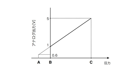
Voltage Output
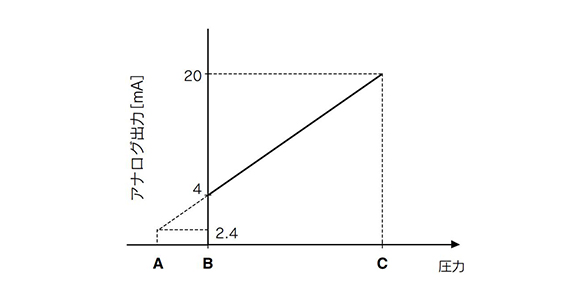
Current Output
| Range | Rated pressure range | A | B | C |
|---|---|---|---|---|
| For vacuum pressure | 0.0 to -101.3 kPa | 10.1 kPa | 0 | -101.3 kPa |
| For compound pressure | -100.0 to +100.0 kPa | - | -100.0 kPa | 100.0 kPa |
| For positive pressure | -0.100 to +1.000 MPa | -0.100 MPa | 0 | 1.000 MPa |
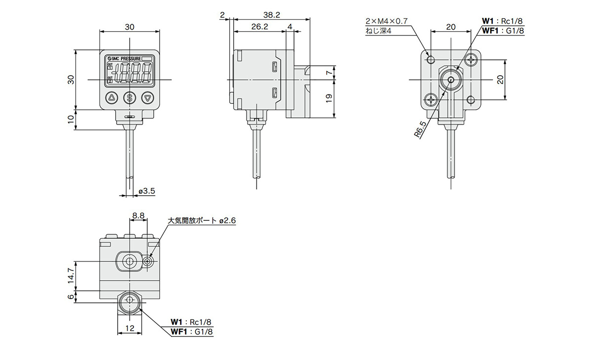
Dimensions (* Please check the product specifications for the details of the lead. )
(Units: mm)

Dimensional drawing of ZSE40A (F) / ISE40A-01/N01
Dimensional drawing of ZSE40A (F) / ISE40A-W1/-WF1
If the open air port of the switch may be blocked by water or dust, etc., it is necessary to insert a tube sold separately into the open air port fully and route the opposite end to a safe place away from water and dust.
* It can be used with TU0425 (material: polyurethane outer diameter is 4 mm, inner diameter is 2.5 mm) for the tube.
Dimensions / for M8 (3 pin) connector
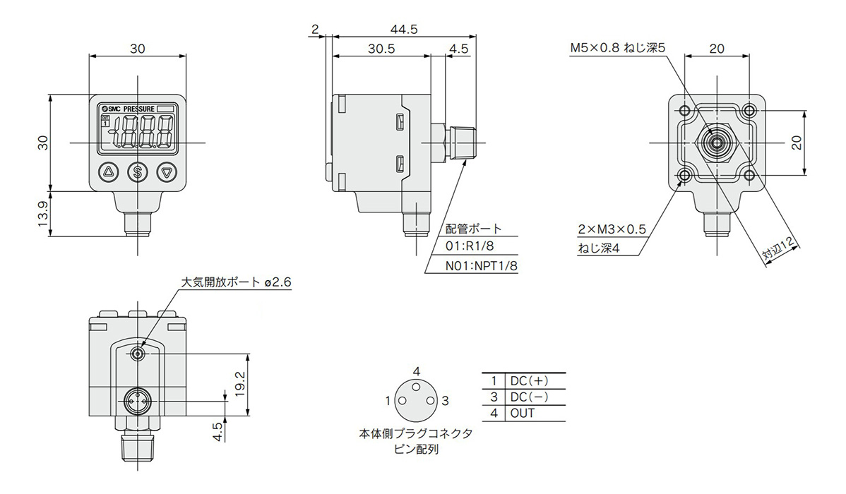
Dimensional drawing of ZSE40A/ISE40A-01-□-□L/-N01-□-□L
If the open air port of the switch may be blocked by water or dust, etc., it is necessary to insert a tube sold separately into the open air port fully and route the opposite end to a safe place away from water and dust.
* It can be used with TU0425 (material: polyurethane outer diameter is 4 mm, inner diameter is 2.5 mm) for the tube.
Body side plug connector pin arrangement
- 1:DC(+)
- 3: DC (-)
- 4:OUT
- *See the SMC catalog for information other than that detailed above.
- *Product pictures are representative images.