3-Position Rotary Table MSZ Series

Caution
- Refer to the catalog for details on product specifications.
- The products shown in the image are representative. CAD data is not supported for some model numbers.
Product Description
SMC Rotary Actuator
[Features]
· 3 stop positions possible
Stop position adjustment range:
From center: ±10°
Rotation range: 0 to 95°
· Handles applications such as sorting workpieces to either left or right
· Can be operated by a single valve
Model Number Notation

Model Number Notation
Specifications of 3-Position Rotary Table MSZ Series
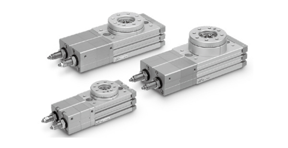
External appearance of 3-Position Rotary Table MSZ Series
| Size | 10 | 20 | 30 | 50 |
|---|---|---|---|---|
| Fluid | Air (non-lube) | |||
| Maximum operating pressure | 1 MPa | |||
| Minimum operating pressure | 0.2 MPa | |||
| Ambient and fluid temperature | 0~+60℃ (No freezing) | |||
| Cushioning | None | |||
| Full swing angle adjustment range | 0 to 190° | |||
| Intermediate position adjustment range | ±10° | |||
| Port size | M5 × 0.8 | |||
Diagram

Structural drawing 1 of MSZ Series (Left figure: MSZA, A high-precision type)

Structural drawing 2 of MSZ Series
| Number | Part Name | Material | Note | |
|---|---|---|---|---|
| 1 | Main body | Aluminum alloy | Anodized aluminum | |
| 2 | Cover | Aluminum alloy | Nickel plated | |
| 3 | Plate | Aluminum alloy | Chromate | |
| 4 | Packing | NBR | - | |
| 5 | Piston | Stainless steel | - | |
| 6 | Pinion | Chrome molybdenum steel | - | |
| 7 | Gasket (For cover) | NBR | - | |
| 8 | Table | Aluminum alloy | Anodized aluminum | |
| 9 | Bearing stopper | Aluminum alloy | Anodized aluminum | |
| 10 | End cover (A) | Aluminum alloy | Anodized aluminum | |
| 11 | End cover (B) | Aluminum alloy | Anodized aluminum | |
| 12 | Cylinder tube (A) | Aluminum alloy | Anodized aluminum | |
| 13 | Cylinder tube (B) | Aluminum alloy | Anodized aluminum | |
| 14 | Tube cover (A) | Aluminum alloy | Anodized aluminum | |
| 15 | Tube cover (B) | Aluminum alloy | Anodized aluminum | |
| 16 | Sub piston (R) | Carbon steel | Nickel plated | |
| 17 | Sub piston (F) | Carbon steel | Nickel plated | |
| 18 | Adjust bolt leveling mount (R) | Carbon steel | Nickel plated | |
| 19 | Adjust bolt leveling mount (F) | Carbon steel | Nickel plated | |
| 20 | Magnet | - | - | |
| 21 | Wear ring | Resin | - | |
| 22 | Bearing | Bearing steel | - | |
| 23 | Basic Type | Bearing | Bearing steel | - |
| High Precision Type | Angular Contact Bearing | - | ||
| 24 | Bushing | - | - | |
| 25 | Bushing | - | - | |
| 26 | Seal Washer | NBR | - | |
| 27 | Piston packing | NBR | - | |
| 28 | Piston packing | NBR | - | |
| 29 | Rod packing | NBR | - | |
| 30 | Gasket | NBR | - | |
| 31 | O-ring | NBR | - | |
| 32 | O-ring | NBR | - | |
| 33 | O-ring | NBR | - | |
| 34 | Compact hex nut | Steel wire | - | |
| 35 | Hex Nut | Steel wire | - | |
| 36 | Hex Socket Head Cap Screw | Stainless steel | - | |
| 37 | Hex Socket Head Cap Screw | Stainless steel | - | |
| 38 | Hex Socket Head Cap Screw | Stainless steel | - | |
| 39 | Cross-Recessed Round Head Screw | Size 10 | Stainless steel | - |
| Brazier head hexagon socket bolt | Size 20,30,50 | Chrome molybdenum steel | - | |
| 40 | Cross-head, No. 0 pan head screw | Steel wire | - | |
| 41 | Push nut | Stainless steel | - | |
| 42 | Parallel pin (Class B) | Carbon steel | - | |
* The manufacturer does not support shipment of individual parts.
Allowable Kinetic Energy and Rotation Time Adjustment Range
| Size | Allowable kinetic energy (J) | Swing time adjustment range that is stable in operation (s/90°) |
|---|---|---|
| 10 | 0.007 | 0.2 to 1.0 |
| 20 | 0.025 | |
| 30 | 0.048 | |
| 50 | 0.081 |
*If operated where the kinetic energy exceeds the allowable value, this may cause damage to the internal parts and result in product failure. Please pay special attention to the kinetic energy levels when designing, adjusting and during operation to avoid exceeding the allowable limit.
Weight
(Unit: g)
| Size | 10 | 20 | 30 | 50 |
|---|---|---|---|---|
| Basic Type | 700 | 1,300 | 1,670 | 2,570 |
| High Precision Type | 730 | 1,400 | 1,790 | 2,730 |
*Values above do not include auto switch weight.
Piping and speed control method
- 1.Use one 3-position pressure center solenoid valve or two 3-port solenoid valves. (Figure 1 or Figure 2)
- 2.Meter-out speed controllers are used for A and B ports and meter-in speed controllers for C and D ports. (Figure 1 and 2 show a state in which the B and D ports are pressurized. )
- 3.Figure 3 shows the details of each operation, and Table 1 shows the pressure port and speed controller for speed adjustment in each operation.

Figure 1: One 3-position pressure center solenoid valve
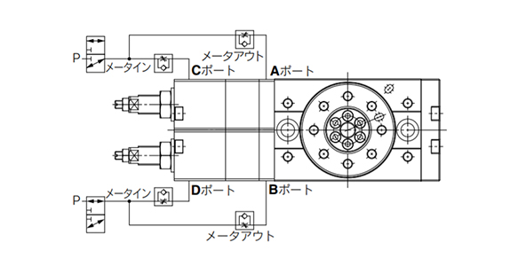
Figure 2: Two 3-port solenoid valves
* The return position of the table when the power supply is cut off differs depending on the solenoid valve used. Refer to the manufacturer's catalog for details.

Figure 3: Each operation content
Speed controller with pressure port and speed adjustment
| Operation | Pressure port | Speed controller | |
|---|---|---|---|
| A,C | B,D | ||
| Clockwise-1 | ● | ● | C port |
| Clockwise-2 | ● | - | B port |
| Counterclockwise -1 | ● | ● | D port |
| Counterclockwise -2 | - | ● | A Port |
Angle adjustment method
1) For this product, adjust each stop position with the adjust bolt leveling mount shown in Fig. 4.
- 1.Adjust bolt leveling mounts a and b are for adjusting the swing end, and adjust bolt leveling mounts c and d are for adjusting the intermediate position.
- 2.Figure 5 shows the angle adjustment range for each adjust bolt leveling mount.
2) Adjust the angle by supplying air to the product. (Low pressure of approximately 0.2 MPa recommended)
- 1.First, adjust the positions of both ends of the swing.
・ Adjust the adjust bolt leveling mount b by pressurizing the A and C ports
・ Adjust the adjust bolt leveling mount a by pressing the B and D ports
After adjustment, lock with the fixing nut. - 2.Next, pressurize all ports A to D to adjust the intermediate position.
・ Loosen the fixing nuts of the adjust bolt leveling mounts c and d.
・ Tighten the adjust bolt leveling mounts c and d to the full extent. (The table can be turned manually. )
・ According to Table 2, operate the corresponding R or L according to the procedure from 1 to 5.
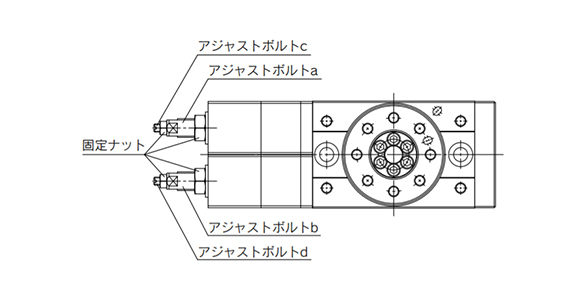
Figure 4: Adjust bolt leveling mount position
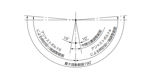
Figure 5: Angle adjustment range
Table 2: Intermediate position adjustment method
| - | R: When adjusting in the clockwise direction | L: When adjusting in the counterclockwise direction |
|---|---|---|
| 1 | Manually move the table counterclockwise until resistance increases. | Manually move the table clockwise until resistance increases. |
| 2 | When the adjust bolt leveling mount d is loosened, the table moves clockwise, so set it at the desired position. | When the adjust bolt leveling mount c is loosened, the table moves counterclockwise, so set it to the desired position. |
| 3 | Loosen the adjust bolt leveling mount c until the resistance increases. (Make sure that the table has no looseness) | Loosen the adjust bolt leveling mount d until the resistance increases. (Make sure that the table has no looseness) |
| 4 | Tighten both adjust bolt leveling mounts c and d by approx. 45°. *1) | Tighten both adjust bolt leveling mounts c and d by approx. 45°. *1) |
| 5 | Lock the adjust bolt leveling mounts c and d with the fixing nut. *2) | Lock the adjust bolt leveling mounts c and d with the fixing nut. *2) |
*1) When tightening the fixing nut, the position of the adjust bolt leveling mount changes by the clearance of the thread, so tighten the change in advance.
*2) If the table has looseness after tightening the nut, readjust it.
Adjustment angle per rotation of angle adjustment screw
| Size | Adjust bolt leveling mount a, b (For edge position adjustment) | Adjust bolt leveling mount c, d (For intermediate position adjustment) |
|---|---|---|
| 10 | 10.2° | 5.1° |
| 20 | 9.0° | 3.6° |
| 30 | 8.2° | 3.3° |
| 50 | 8.2° | 4.1° |
* Instructions for piping, speed control method, and angle adjustment method are included in the product.
Notes
Product Mounting Direction
There are no restrictions to the mounting direction of the product, but if the gravity acting on the load acts in the rotating direction of the table (for example, when the rotary shaft is horizontal and the center of gravity of the load does not match the rotation center), the rotational speed will become unstable.
In particular, the speed from the end position to the intermediate position is controlled by meter-in. Therefore, if this operation direction matches the direction of gravity, acceleration due to gravity cannot be suppressed and bouncing may occur when stopped.
On the Play of the Table in the Middle Position
By properly adjusting the intermediate position, play in the rotation direction of the table can be suppressed. However, as the number of movements increases, play (approx. 0.1°) may occur, so if there is a problem in use, readjust the intermediate position again.
- *See the manufacturer's catalog for product information other than the above.
- *The product image is a representative image only.