Pin Cylinder, Double Acting, Single Rod CJP2 Series
Caution
- See catalog for specification details.
- Product pictures are representations. CAD data is not supported for some model numbers.
Product Description
An air cylinder that can be connected to ø2 (2‑mm diameter) one-touch fittings.
[Features]
· Can be connected to a speed controller.
*See the manufacturer's catalog for detailed specifications.
*Product pictures are representations. CAD data is not supported for some model numbers.
Pin Cylinder, Double Acting, Single Rod CJP2 Series Specifications

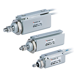
Pin Cylinder, Double Acting, Single Rod CJP2 Series external appearance

Double acting / Single rod, rubber bumper image
| Operating method | Double acting, single rod | |
|---|---|---|
| Maximum operating pressure | 0.7 MPa | |
| Minimum operating pressure | ø4 (diameter 4 mm) | 0.15 MPa |
| ø6 (diameter 6 mm) | 0.12 MPa | |
| ø10 (diameter 10 mm), ø16 (diameter 16 mm) | 0.06 MPa | |
| Proof pressure | 1 MPa | |
| Ambient and working fluid temperature | Without auto switch: -10°C to 70°C, With auto switch: -10°C to 60°C (No freezing) | |
| Lubrication | Not required (non-lube) | |
| Stroke length tolerance | +1.0 0 | |
| Rod-end configuration | With thread, without thread | |
| Operating piston speed | 10 to 500 mm/s | |
| Cushioning | Rubber cushion | |
| MountingNote) | Basic, flange, foot, clevis, trunnion | |
Note) Bore size of ø4 (4‑mm diameter) is available with basic mounting only. The piston speed for a bore size of ø4 (4‑mm diameter) is 50 to 500 mm/s.
Weight list
(Unit: g)
| Stroke (mm) Mounting | Tube Internal Diameter (mm) | ||||
|---|---|---|---|---|---|
| 4 | 6 | 10 | 16 | ||
| Basic Weight List | 5 | 11 | 16 | 27 | 42 |
| 10 | 13 | 18 | 29 | 46 | |
| 15 | 15 | 21 | 32 | 50 | |
| 20 | 17 | 23 | 35 | 54 | |
| 25 | - | 25 | 37 | 58 | |
| 30 | - | - | 40 | 63 | |
| 35 | - | - | 43 | 67 | |
| 40 | - | - | 45 | 71 | |
| Bracket weight | Flange | - | 5 | 6 | 16 |
| Foot | - | 7 | 9 | 24 | |
| Clevis Shape | - | 2 | 5 | 8 | |
| Trunnion (with pin) | - | 15 | 25 | 70 | |
| Additional weight for built-in magnet | 2 | 3 | 5 | 7 | |
Standard stroke
| Bore size (mm) | Stroke (mm) |
|---|---|
| 4 | 5, 10, 15, 20Note) |
| 6 | 5, 10, 15, 20, 25 |
| 10, 16 | 5, 10, 15, 20, 25, 30, 35, 40 |
Note) 20 stroke of bore size 4 mm is standard type only.
Standard Equipment Accessories
| Mounting | Accessories | ||
|---|---|---|---|
| Mounting nut (1 pc.) | Rod-end nut (2 pcs.) (with thread) | Trunnion (with pin) | |
| Basic type | ● | ● | - |
| Flange | ● | ● | - |
| Foot | ● | ● | - |
| Clevis Shape | - | ● | - |
| Trunnion | - | ● | ● |
Dimensional Outline Drawing: Basic Mounting (ø4)
(Unit: mm)

Standard: CJP2B4 dimensional drawing

Without rod-end thread (CJP2B4)

Built-in magnet: CDJP2B4 dimensional drawing

Without rod-end thread (CDJP2B4)
Dimensional Outline Drawing: Basic Mounting (ø6 to ø16)

Standard: CJP2B6 to 16 dimensional drawing

Without rod-end thread (CJP2B6 to 16)
(Unit: mm)
| Tube I.D. | Symbol | |||||||||||||||||||
|---|---|---|---|---|---|---|---|---|---|---|---|---|---|---|---|---|---|---|---|---|
| A | A’ | B | B1 | B2 | C | D | E | F | F’ | GA | GB | H | J | MM | NN | P | S | W | Z | |
| 6 | 7 | 9 | 14 | 14 | 5.5 | 2 | 3 | 16.5 | 8 | 6.5 | 5.5 | 6.5 | 17 | 6 | M3 × 0.5 | M10 × 1.0 | M3 × 0.5 | 16 | 3 | 33 |
| 10 | 10 | 12 | 15 | 17 | 7 | 2.5 | 4 | 19 | 8 | 6.5 | 6 | 7 | 20 | 7 | M4 × 0.7 | M12 × 1.0 | M3 × 0.5 | 19.5 | 3 | 39.5 |
| 16 | 12 | 14 | 20 | 19 | 8 | 3 | 6 | 24.5 | 10 | 8.5 | 6.5 | 7.5 | 24 | 10 | M5 × 0.8 | M14 × 1.0 | M5 × 0.8 | 19.5 | 4 | 43.5 |

Built-in magnet: CDJP2B6 to 16 dimensional drawing

Without rod-end thread (CDJP2B6 to 16)
(Unit: mm)
| Tube I.D. | Symbol | |||||||||||||||||||
|---|---|---|---|---|---|---|---|---|---|---|---|---|---|---|---|---|---|---|---|---|
| A | A’ | B | B1 | B2 | C | D | E | F | F’ | GA | GB | H | J | MM | NN | P | S | W | Z | |
| 6 | 7 | 9 | 14 | 14 | 5.5 | 2 | 3 | 16.5 | 8 | 6.5 | 5.5 | 6.5 | 17 | 6 | M3 × 0.5 | M10 × 1.0 | M3 × 0.5 | 21 | 3 | 38 |
| 10 | 10 | 12 | 15 | 17 | 7 | 2.5 | 4 | 19 | 8 | 6.5 | 6 | 7 | 20 | 7 | M4 × 0.7 | M12 × 1.0 | M3 × 0.5 | 24.5 | 3 | 44.5 |
| 16 | 12 | 14 | 20 | 19 | 8 | 3 | 6 | 24.5 | 10 | 8.5 | 6.5 | 7.5 | 24 | 10 | M5 × 0.8 | M14 × 1.0 | M5 × 0.8 | 24.5 | 4 | 48.5 |
*See the manufacturer's catalog for product information other than the above.